A practical guide

by SV3ORA
Experiments on square loop toroids
A practical guide
by SV3ORA
Preface
This page presents my experiences and my experiments on square loop toroidal cores. Since square loop toroids are bistable devices, they were used for storing bits of data in magnetic core memories, but also in performing logic functions on less commonly found magnetic core logic circuits. Whereas the magnetic core memory technology is well known and established, since it was used for quite a few decades, little is known about the magnetic core logic circuits. It seems that the development of such circuits was abruptly stopped at some point, for the shake of the new coming transistor logic.
To revive such old techniques is not easy. I faced many challenges mainly due to the lack of information. Another issue was the lack of the specific square loop toroids models, mentioned on the old literature. Here, I present my experiences, so you do not have to reinvent the wheel yourself.
Where to find square loop toroids?
Eventually and after lots of search, I found that square loop toroids are still produced today, although they are not as common as they were on the past. Their main purpose is not digital applications but magnetic amplifiers/regulators and saturated reactor applications.
If you have a desktop computer at home, you probably have already a square loop toroid. Many switching computer power supplies have at least one square loop toroid inside, that is used as a magnetic amplifier/regulator. These are mainly metallic ribbon (tape wound) types, but I have also seen ferrite/ceramic ones. Ferrite ones, look like ordinary ferrite cores, usually with a coating on them. Metallic ribbon ones have a plastic outer body, with a metallic ribbon spiral inside. Some metallic ribbon cores, allow the plastic to be easily taken apart by hand and you would be able to notice the spiral ribbon inside. To identify such cores inside a computer SMPS, look for a toroid (plastic or coated) near the heatsinks that has low number of turns (usually less than 10 or so) of thick diameter wire on them.
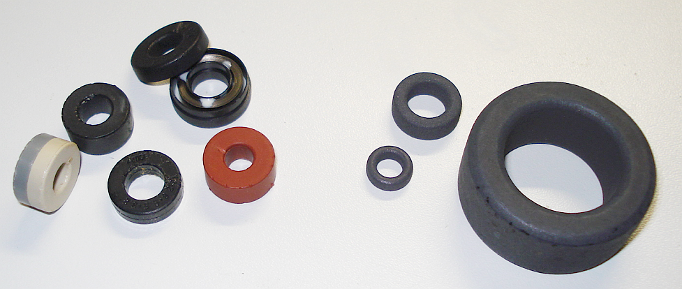
Square loop toroids.
Left, metallic ribbon (tape wound) types. One of them is shown open.
Right, ferrite/ceramic type (Ferroxcube).
Besides computer power supplies, there are quite a few companies that still produce square loop toroids, such as mag-inc and ferroxcube. I will mainly focus on Ferroxcube ones as these cores can be currently found on ebay (expensively) and farnell. Ferroxcube produces different sizes of cores that use 3R1 material to make square loop toroids.
TN9/6/3-3R1
TN10/6/6-3R1
TN13/7.5/5-3R1
TN14/9/5-3R1
TN17/11/11-3R1
TN23/14/7-3R1
TN36/23/15-3R1
TN9/6/3-3R1 is the smallest size and TN36/23/15-3R1 the largest. For digital applications and for minimum power requirement and cost, I mainly consider the use of TN9/6/3-3R1.
How to calculate the current and number of turns to switch the cores?
The procedure of finding the point at which the core magnetization will be switched from one direction to the other, is the most important step in characterizing your cores. This procedure is similar for all square BH loop toroids, but for the purpose of the explanation, I will mainly consider the TN9/6/3-3R1.
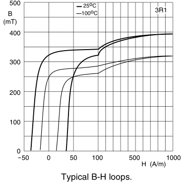
Typical BH loops for 3R1 material, are shown above. The horizontal axis represents the field strength (H) and the vertical axis the induction (B). The field strength is the force that needs to be applied to the core to cause it's magnetization. This force depends on the number of turns (N) on the core and the current through these turns (I). The greater the number of turns or the greater the current, the greater the field strength and as a result, the greater the magnetization of the core. Or put it the other way, if you double the number of turns, you can halve the primary current to obtain the same field strength.
The field strength is given by the formula H=I*N/lc
where:
H = field strength (A/m)
I = coil current (Amperes)
N = number of coil turns (1,2,3 etc)
lc = magnetic length of the core (Meters)
Let's consider an example using the TN9/6/3-3R1 core wound with 20 turns of enameled copper wire. For this example we will randomly assume a current of 350mA (0.35A). In TN9/6/3-3R1 lc (referred as effective length le in the datasheet) is 22.9mm (0.0229 meters). By solving the formula above, we find H to be approximately 306 A/m. If you look at the BH diagram, you can see that this setup is able to fully switch the core. In fact, 306 A/m is too high and thus you can safely reduce even more the number of turns or the current and the core will be possibly still switched.
Verifying your calculations on the oscilloscope
To verify your calculations, you can build the simple circuit shown below. The number of turns you have previously calculated, are wound on the core primary. An identical secondary winding, with the same number of turns, is wound on the core. The created transformer is then connected as shown.
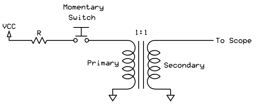
Simple circuit for
testing core switching
The output of the transformer is connected to a digital storage oscilloscope. The oscilloscope is set to be triggered on the first rising edge. The closing and the opening of the momentary switch, creates a pulse with a rising edge at it's beginning and a falling edge at its end, but it also introduces spikes and noise. You need to focus only on the first true rising edge and ignore the falling edge and any spikes.
You can force the scope to be triggered on the first rising edge and ignore all the following triggers by setting a trigger hold off time, if this is an available option. Also you can avoid the false triggering from the spikes by setting a higher trigger level on the scope. These settings will allow you to see the desired waveform that is caused by the core switching only and on the other hand, ignore of any spikes caused by the momentary switch action and the switch release. The scope will only be triggered on the first true rising edge of the pulse and the appropriate stored waveform will be displayed.
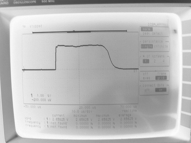
When the setup is ready and the scope trigger is armed, press and release the momentary switch instantly. If core switching occurs, you should see a waveform similar to the one below. You will notice a short pulse at the beginning, caused by the rising edge and then a much longer pulse, as a result of the core switching. I have found that the lower the current, the longer this pulse is. Your pulse may be negative, depending on the phasing of the windings or the polarity of the PSU.
If you do not notice this kind of waveform, your core may be switched already in the direction you try to switch it, or the current is insufficient for switching to occur or the horizontal setting of the scope causes the display to zoom too much. First, try to swap the polarity of the PSU and send another pulse. Swap PSU polarity again and again and send only one pulse after each swapping. If you still cannot notice such a waveform then freeze the video on the scope and search in the whole recorded sample to locate the waveform, as your horizontal setting may zoom the window too much and the scope may trigger out of this window. If you still cannot find the waveform of interest, the current is probably insufficient for core switching to occur. Try increasing the current and repeat the process again.
I have verified that this waveform shape is the result from the core switching, from three facts. First, it occurs only on the first pulse, after each PSU polarity swapping. If you send a second pulse, you will not get this waveform this second time, because the core is already switched in the direction you try to switch it. The waveform you will get from applying a second pulse, is more like the responce from the rising edge of the applied pulse to the transformer winding (a short output pulse, not stretched).
The second fact is by trying different types of known cores. All the known square BH loop cores that I have tried, output the kind of waveform shown in the picture above, a well defined, elongated, more like square shaped output pulse, with a smooth S-shaped decay. On the other hand, all the known non-square BH loop cores that I have tried, output a short pulse only. In some of these non-square BH loop cores this short pulse is more like a reverse sawtooth or a capacitor discharge waveform, elongated a little bit, but not like the waveform of the square loop toroids. In fact, I have been found to be fun to switch unknown cores and see if they are square loop ones or not.
The third fact is based on two sources, a 1976 issue of the Byte magazine, which refers to magnetic core memories and a very interesting unclassified millitary document.
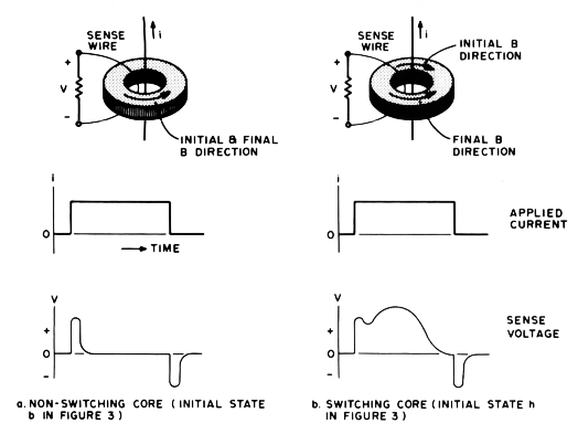
According to these documents, this kind of waveforms occur only if the core is initially switched (magnetized) in one direction and a powerful enough pulse causes it to switch in the other direction. In the picture above, the negative spike from the falling edge of the pulse is also shown, but in our case we have set the scope to ignore this spike.
Calculating the current limiting resistor
To be continued...