How to produce X-rays: PD500 tubes
Subsection PD500
The PD500 tube is a "beam triode" used in old TV's to regulate the
acceleration voltage for the CRT. As such, it is specified for 25kV and 30W
max. anode dissipation. Good tubes take up to 70kV without cold cathode
discharge. This makes it possible to choose acceleration voltage (penetration
power) and anode current (intensity of x-rays) indepently. Also, output
intensity is much higher than with rectifiers. One disadvantage is that
radiation is produced inside the anode cylinder and has to pass it to get out.
Internal structure of the PD500
The PD500 is a simple triode designed
for very high operation voltage (25kV) at a maximum anode power dissipation of
30W.
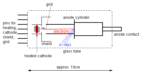
Electrons heated off the cathode are probably focused by the
shield into the anode cylinder and hit the plate. The x-rays produced here have
to pass the anode and the glass and so are considerably filtered.
Making the tube HV-proof
Although designed for 25kV (and so being
relatively large), it is a good idea to take some extra effort to prevent
arc over and corona, which might destroy the tube and are a nuisance anyway.
I found that the tube just fits into the rubber sealing of a certain kind of
waste-water pipe (PP, for indoor use):
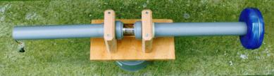
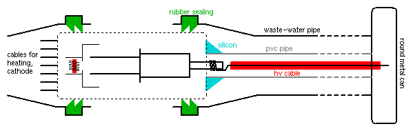
The round metal can serves as HV terminal (prevents spraying). The additional
insulation with pvc pipe (grey) and silicon around the anode lead is not
essential, the waste-water pipe is enough. The big advantage of this
construction is that, when testing many tubes, they can be changed easily.
Lead case for proper shielding (added Sep 28 1998)
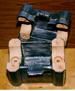
I
constructed a lead case around the wooden mounts. It consists of a double layer
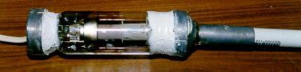
of 1mm lead sheet. To shield radiation near the tube axis, I glued lead caps
that just fit into the plastic pipe directly on the tube (with silicone rubber).
This also improved the insulation at the hv end - the rubber sealings of the
plastic pipe didn't do their job with all the metal around.
Operating the tube
I use the tube with my 100kV
cascade and 8kVss
supply driven by a variac. The anode contact gets 100kV max. from the
cascade, all other pins except one of the two heating pins are grounded. The
heating current (about 200mA) is supplied by an ordinary lab power supply, with
some additional resistors in series. The heating current determines the cathode
temperature, and this in turn the anode current. Note that the temperature
follows the heating current with a large delay, you have to increase it very
carefully and slowly. I usually choose 300uA anode current at 60kV (18W) - at
700uA, the anode begins to glow red and the tube gets very hot, and at more than
60kV I get cold cathode discharge (which I am afraid might damage the tube).
Shielding becomes a problem at the high radiation levels available with this
tube. There are two main reasons for this:
- Radiation (back-)scattering by walls etc. It seems it is not enough to
shield just one side of the tube (the one which goes towards you), when the
other side points to a near wall. A considerable amount af radiation is
reflected back to you by the wall. The consequence must be to make a nearly
complete shield with only a narrow beam getting out.
- Absorption coefficients drop rapidly with increasing energy of the x-rays.
1mm lead is not enough here, neither are 10cm concrete. In particular, I
noticed that when I increase the operation voltage above about 55kV, the level
of radiation that comes through a concrete shielding rises significantly.
In my experimental setup
I put a heap of concrete paving stones around the tube, placed myself and the
control instruments at 2m distance and still didn't dare to stay there for long.
Output power estimates
At 60kV and 300uA, I measured up to 5mSv/h in
50cm distance (using a surplus dose meter). This is extremely high - 200h near
the tube would be enough to cause serious radiation syndrom. It is about 30
times as much as the maximum output of my DY802 (see the DY802
dose rate
measurement), although some doubt is appropriate here, as I used different
meters, and both were not really good for x-rays.
The direction of maximum output seems to be not rectangular to the tube axis,
but somewhat towards the cathode, as indicated in the diagram above.
In an experiment to produce Laue pictures of a CaCO3-crystal (which didn't
work), I exposed a film (Kodak Biomax) at 73cm distance for 2h to radiation that
went through about 2cm crystal. The result was a spot of about the same grey as
an exposure to a DY802 at 11cm distance for 5min without crystal. So the PD500
radiation with crystal is still about twice as high as that from a DY802 without
(DY802 driven at 10uA, 45kV).
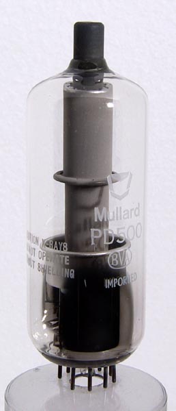
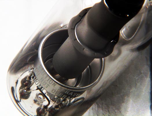
Here are two PD500 photos: