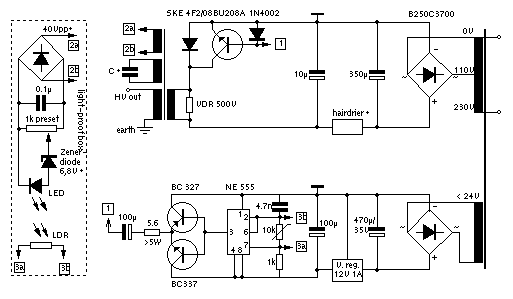
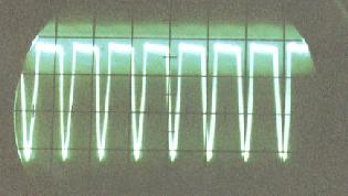
 This is the circuit diagram of my version together with an
oscilloscope screenshot (probed across the primary flyback winding, parallel to
the VDR; 200V/div. vertical, 50us/div horizontal). (NOTE: VDR = Voltage
Dependent Resistor = MOV = Metal Oxide Varistor!) The hairdrier protects the
BU208A from overload. It makes it possible to virtually short-circuit the output
without the transistor getting too hot. Instead, the heat is dissipated by the
hairdrier. The diode SKE 4F2/08 can be replaced by any fast-switching diode
capable of about 3A/800V. There's also a version BU208D of the transistor with a
diode integrated, but it's more expensive, and I haven't tested it. The best way
to find out the correct terminals of the flyback is to have a circuit diagram of
the TV it comes from; the second best is simply to try every combination (using
a variable transformer to turn up "mains" voltage slowly, so nothing is
damaged). The value of C depends on your flyback and which winding you use. Use
one with about 1000V output and around 1nF for the cap. The VDR is essential,
without it your BU208A will die with the first spark. But the whole regulation
circuit (on the left) is optional, you have to adjust the frequency by hand
anyway. A more detailed description how it works and how to adjust it will
follow sometime, I hope. Email me if you want to know more.
This is the circuit diagram of my version together with an
oscilloscope screenshot (probed across the primary flyback winding, parallel to
the VDR; 200V/div. vertical, 50us/div horizontal). (NOTE: VDR = Voltage
Dependent Resistor = MOV = Metal Oxide Varistor!) The hairdrier protects the
BU208A from overload. It makes it possible to virtually short-circuit the output
without the transistor getting too hot. Instead, the heat is dissipated by the
hairdrier. The diode SKE 4F2/08 can be replaced by any fast-switching diode
capable of about 3A/800V. There's also a version BU208D of the transistor with a
diode integrated, but it's more expensive, and I haven't tested it. The best way
to find out the correct terminals of the flyback is to have a circuit diagram of
the TV it comes from; the second best is simply to try every combination (using
a variable transformer to turn up "mains" voltage slowly, so nothing is
damaged). The value of C depends on your flyback and which winding you use. Use
one with about 1000V output and around 1nF for the cap. The VDR is essential,
without it your BU208A will die with the first spark. But the whole regulation
circuit (on the left) is optional, you have to adjust the frequency by hand
anyway. A more detailed description how it works and how to adjust it will
follow sometime, I hope. Email me if you want to know more.
As I said, this device is designed to feed TV cascades, and it does this much more efficiently than the above 5kV mains transformer (due to the higher operating frequency). You can draw a very hot arc from it as well. So if you have the necessary knowledge, it's really worth the labour (and price), especially when used with the 80kV super-cascade .