A simple, failure immune 4-bit
digital computer made out of common TTL chips
by SV3ORA
Introduction
I always wanted to build a
simple computer system out of common TTL chips but the complexity and cost was
the main obstacle. Eventually, I found a project on the
homemade CPU ring which described the construction of a 4-bit CPU out of TTL
chips. Despite most of such articles are quite complex to understand and
confusing to navigate through their pages, this article was so well written and
so complete that I could entirely understood how the CPU worked on a single
website reading. This inspired me to build my own version of it.
This CPU used mostly common TTL
chips apart from the EPROMs and the RAM chips. I decided to build my own
militarized version of it first and later on to try to make modifications to it.
The main modifications which I felt I needed to make, were to replace the EPROMs
and RAM, to use entirely TTL or more standard parts. This is a project that is probably
going to take years to complete properly.
This is a slow and very limited
usage computer system and it has been basically rebuilt by me for educational
purposes and components reliability demonstration. There are not such things as
keyboard and screen, if you want a such computer, build the ZX-80 that I have in
another section on my website, or other such computers that I will include on
the website. You may think of it more like a microcontroller
rather than a computer. It is programmed to do a single job, using machine
language code entered mainly using front panel switches, much like the
MITS Altair
8800. There is no prepackaged CPU though. The CPU is mage out of common TTL
chips.
There is no need to repeat
everything here. Download an read the project articles first, to understand how
the computer works. Then follow my page below to see how to make a rugged
version of this computer, that uses more standard parts, it is failure immune
and can work for many years of reliable operation.
Electronics Parts List
There was no electronic
components parts list for
this project. There were some gates that were not marked in the schematics the
author provided, so I decided to make my own parts list by carefully examining
these schematics. Since I was interested in immunity to failures due to physical
factors, I used more rugged components. Here is the parts list including the
"missing" TTL chips. The actual components used are listed. You may
substitute some of them with your versions if rigidity is not your goal. For
example you can substitute the F series semiconductors with the LS series and
the military switches with cheap ordinary ones.
| Part |
|
Quantity |
| 10uF |
|
1 |
| 0.47uF |
|
1 |
| 0.001uF |
|
1 |
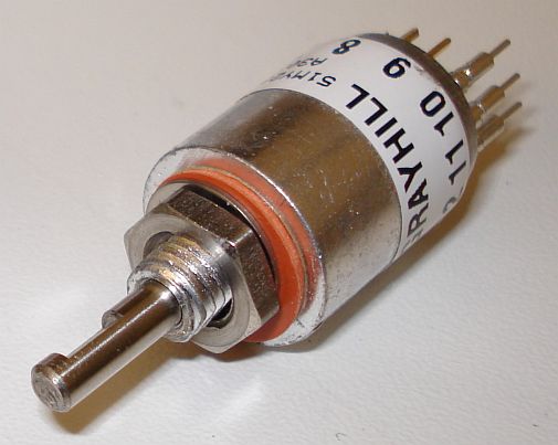
| 1-pole 3-position switch
Grayhill
3 position switch. Model: 51MY23691. Has 12 tabs and center ground.
NSN: 5930-01-304-4991
Position 1: Pin 2 to center ground.
Position 2: Pin 3 to center ground.
Position 3: Pull center rotor and
rotate. Pin 1 to center ground - other positions locked out. |
 |
2 |
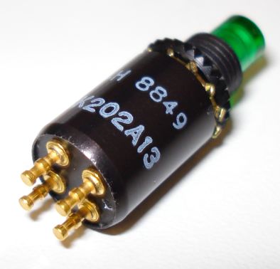
| Push-to-make program
write switch. Auto-return switch
Cutler Hammer, Part
Number: 173K202A13 NSN: 5930-01-336-7686
National Item Identification Number
01-336-7686
013367686
5930-01-336-7686
5930013367686
Reference Numbers (Part Numbers)
173K202A13
7920101-00 |
 |
1 |
| ON-OFF power switch
NKK locking switch
Model: NKK S-1AL
Datasheet |
|
1 |
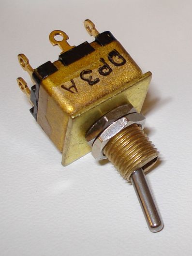
| ON-OFF data,
instruction and address switch.
Torbal DP3A or DP3.
VERTEX INDUSTRIES INC
TORBAL DIV
Part numbers:
DP3A
DP3A
L218796-4
SMC134494-3
T#DP3A |
 |
16 |
| LED |
|
32 |
| 0.1uF |
|
30 |
| 0.22uF |
|
4 |
| Beckman 898-3-R300 (or 899-3-R300) |
|
1 |
| Beckman 898-3-R3K (or 899-3-R3K) |
|
1 |
| Beckman 898-3-R4K7 |
|
2 |
| Beckman 898-3-R1K |
|
4 |
| 54F244 |
|
6 |
| 54F240 |
|
3 |
| 54F32 |
|
1 |
| 54F08 |
|
3 |
| 54F193 |
|
1 |
| 54F85 |
|
1 |
| 54F670 |
|
1 |
| 54F175 |
|
4 |
| 54F624 |
|
1 |
| 54F93 |
|
1 |
| 54F161 |
|
1 |
| 54F374 |
|
1 |
| 54F74 |
|
2 |
| 2114 (or 2112) |
|
2 |
| 27C16 |
|
2 |
Schematics and PCB
There were schematics on the author website but
these were only rough images, pin numbers, coupling capacitors etc are missing. Also there was no PCB for the project. I contacted the
author if he had any CAD files, but I did not get a response. For these reasons,
I have decided
to make my own PCB. My version will include monitoring of the I/O
with LEDs as well as some other possible changes.
There was a great decision I had to get in
building this computer. Build the whole thing onto one PCB or split all computer
modules into different PCBs. Splitting modules according to their role on the
computer system gives greater flexibility. One can change modules by replacing
them with more updated versions, as long as I/O connections stay the same,
without having to replace the whole PCB of the computer. On the other side, lots
of cabling is required between different modules. We are making a PCB for this
computer because we want easier construction with less cabling, which will lead
to a more rugged system. Why to build PCBs if you have lots of cables to
interconnect them?
If you build the project as a KIT, then you
should include everything in one PCB for cost reasons. But if you build the
project only once like me, you should better split the modules into separate
PCBs. This will allow you to alter them and experiment later on, without having
to rebuild the whole computer.
Regarding the PCBs, I have tried to include as
much traces at the bottom layer as possible. That way, if one decides not to
build double sided PCBs, he could join the top layer traces using wires. This
ensures that reproduction can take place even if an advanced PCB fabrication lab
is not available.
Anyway, here are the PCBs and my modifications
for the computer so far:
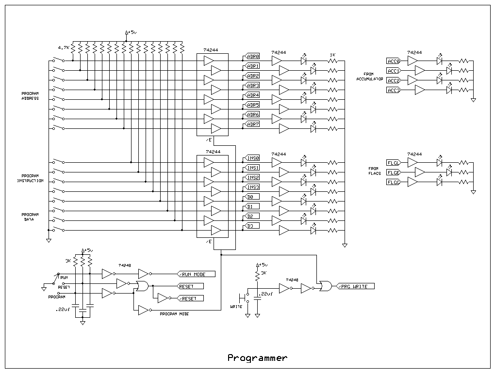
Programmer
ExpressPCB CAD file
Top copper layer (PDF)
Bottom copper layer (PDF)
Silkscreen layer (PDF)
Modified programmer schematic (WRITE switch disabled during RUN mode)
Back to main site
Homebuilt CPUs WebRing
JavaScript by Qirien Dhaela
Join the ring?
David Brooks, designer of the Simplex-III homebrew computer, has founded the
Homebuilt CPUs Web Ring.
To join, drop Dave a line,
mentioning your page's URL. It will then be added to the list. You will also need to copy this code fragment into your page.