An ultimate
quality shortwave transceiver
by SV3ORA
Preface
This is my try to make an all homemade transceiver for the HF bands. I always wanted to do so, but having seen many designs throughout the years, I could not decide the way to do it. Now that I feel more confident about these designs I have finally decided to make the transceiver.
Special care has been taken so that the final product is a quality transceiver. My personal perception is that quality does not necessarily mean easiness of use, nice digital displays, DDS solutions and so on, but other things, such as low noise, low distortion, high dynamic range etc. There are many ways to build such a transceiver, but my experiments are based on discussions I had with other people and the articles I have red throughout the years. From these articles and discussions, I distinguished some bright ideas, which I am trying to implement on this transceiver. I am planning to use this transceiver, to beat commercial ones, so the end result should be a complete working transceiver and not just boards hanging around.
I will update this page continuously as I build and test things, so check it out often.
General overview
This is what I have thought of the overall system so far.
The local oscillator design
All-band local oscillator design
The all-band local oscillator is based on analogue synthesis and filtering, to ensure ultra low noise, high unwanted signals suppression, constant output signal level and at the same time using only discrete components commonly found in a lab.
Ten ultra low noise XOs, followed by LPFs to cut off higher harmonics, are used to cover all ten radio amateur bands. The RF outputs are switched accordingly to the second mixer.
Another ultra low noise XO, followed by an LPF, is mixed with a very low noise VFO, followed by an LPF as well, and the output of this first mixer is connected to the second mixer, through a BPF.
The output of the second mixer is switched accordingly to BPFs to keep only the wanted band signal.
The XOs have very high short-term frequency stability, but long-term temperature changes can cause frequency drift. Nevertheless, crystal ovens were not used in this design, for several reasons.
One could use a single VFO and mix it with each switched XO, to produce the desired frequency. The VFO should then be of a high frequency (around 17-18MHz), in order to cover all HF bands, if commonly available crystals are to be used. The reason for using another XO mixed with the VFO to produce this high frequency signal, is frequency stability. Instead of using a high frequency VFO directly, which is prone to frequency drifting, use a low frequency stable VFO and mix it with an intermediate frequency XO, to produce the high frequency signal. This signal will now be very stable and it's stability is mainly defined by the stability of the low frequency VFO.
One could also use a single (or just a few) XO and having the band crystals switched to it, in order to avoid to use 10 XOs (to be continued)
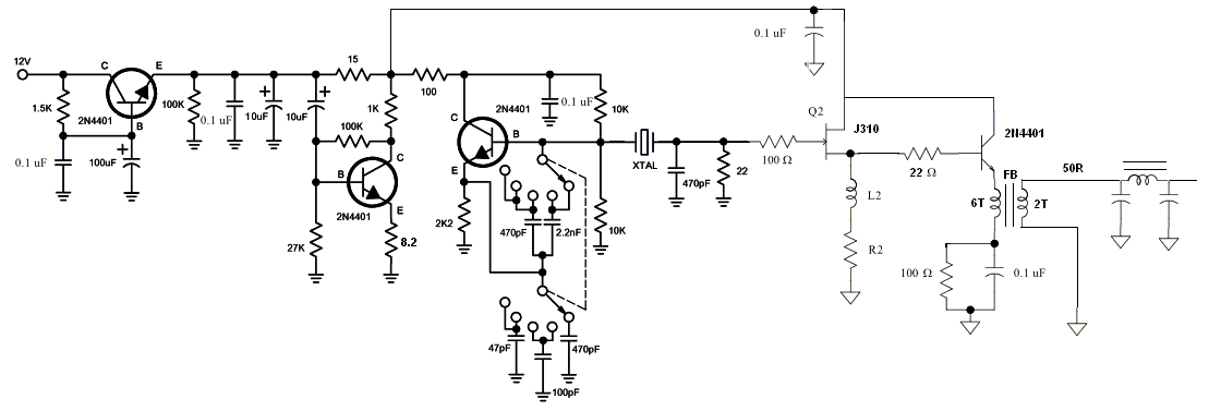
Bands oscillators
Here are the different bands crystal oscillators and LPFs.


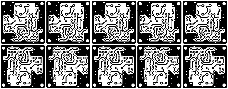
Multi oscillator PCB files
To be continued...