HF+6m active antenna for the Kenwood TH-F6/TH-F7
and all VHF/UHF handhelds with HF receiving capability
by sv3ora
This active antenna, is my design and it uses the Mini Circuits PGA-103+ MMIC as the amplifying element. The datasheet of this IC, specifies operation to 3-5V and for frequencies of 50MHz and up, at 50 ohm. However the IC can operate at much lower frequencies, it is just that the datasheet does not specify 50 ohm operation at these frequencies. The preamplifier antenna I used, is capacitive and it is not 50 ohm anyway. The circuit of my active antenna is shown below and it is designed with several points in mind.
 |
|
|
|
|
|
|
|
|
|
|
 |
 |
|
|
|
|
|
|
|
|
|
|
|
|
|
|
|
|
100nF |
 |
 |
1.2V |
Ni-MH LSD |
|
|
|
|
|
TX ant |
|
|
|
|
|
|
|
 |
 |
 |
 |
|
|
|
|
|
RX ant |
|
 |
|
100nH |
|
220nH |
|
100nH |
|
|
270uH |
 |
pga 103+ |
100nF |
|
|
|
4t FB43 -101 |
|
 |
 |
|
 |
 |
|
|
|
|
|
|
|
 |
|
|
|
|
|
 |
| in/out | |
470nF |
100pF |
 |
100pF |
|
2x |
 |
 |
100nF |
|
|
2x |
|
|
 |
10k |
|
|
|
|
|
|
|
|
|
|
|
|
|
|
|
|
|
|
|
|
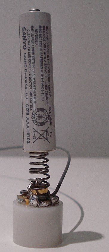
The size and the weight of the antenna was the limitation for my design. My intention is to include the preamplifier AND the battery inside a tube that will be connected in series with the rubber antenna of the radio. This will make an overall very low profile antenna and one would hardly notice that there is one attached to the radio. It would just seem to be a more elongated rubber antenna. No external enclosures, batteries and funny appearance. Ultimate portability, ruggedness, and professional look, just like the radio itself.
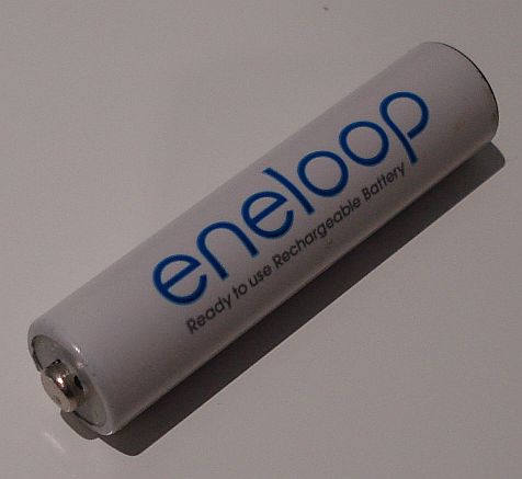
This limitation, possesses a series of critical design considerations. The battery availability, cost, type, size and weight, as long as the preamplifier operating voltage and current, are among the most important ones. Most preamplifiers, require more than 9V to operate, so a 9-volt battery or an A23, are the first to come in mind. However, the 9-volt battery is too big and the A23 can provide a very small current, which makes their use inappropriate for this design. A lower voltage battery, such as the AAA could be used, but an inverter would then be needed. Inverters operate at high frequencies and their harmonics and noise can reach all the way up to HF, so these are to be avoided for such an antenna, attached so close to the radio. Hopefully, I have found the PGA-103+ to operate very well at 1.2v and even down to 0.6v! The amplification difference from 3.7v to 1.2v is only 2 S-units at the receiver meter, so it has been thought to be not a very important compromise. The choice of 1.2v as the operating voltage for the active antenna possesses significant advantages. A rechargeable AAA low self-discharge Ni-MH battery could be used, which is commonly available, cheap and of small size. Moreover, it has significant current capability and my tests have shown that it can hold the preamplifier up and running for very long. You would probably recharge the Li-ion battery of the radio many times, before the active antenna battery needs recharging.
A limitation from using such a low voltage, is the switching of the active antenna. I needed an active antenna, that could be used along with the radio main rubber antenna. This way, I could receive using my active antenna, but at the same time I could transmit using the rubber antenna, without having to remove the active antenna from the radio every time. Initially, the rubber antenna of the radio was thought to be used as the antenna element for the preamplifier, along with low voltage relays for the switching between TX and RX. But even these relays, cannot operate at such a low voltage. Moreover they consume significant power and drain the battery, unless latch types are used, which would make the circuit much more complex and big. Since the RX antenna is mainly capacitive in such low frequencies, I thought to use a second antenna instead of the rubber. This antenna, would be a metal tube (capacitive) and it would double as the preamplifier and AAA battery enclosure, so that no extra size is added to the overall active antenna. With this little trick and having in mind that the radio cannot transmit on 6m and below (where an active antenna is needed the most, due to size limitations), I built a LPF at the output of the active antenna, which is used in an ingenious way. To better understand this, I describe the signals flow below.
During receive, the RX antenna (capacitive metal tube) passes all signals to the input inductor, which in turn filters out the VHF and higher frequencies. The anti-parallel diodes are used as a protection from static discharges and very high input signals. Then the signals are passed to the PGA-103+ which amplifies them. The amplified signals, are then passed through the anti-parallel diodes (used for the same purpose like before) to the 6m LPF and all signals below 6m, are then passed to the input of the radio. The LPF, also helps in reducing the intermodulation products caused by strong VHF/UHF transmitters. The rubber antenna of the radio, connected in parallel with the active antenna, has no effect as it is not sensitive.
During transmit, the output signal of the radio (VHF/UHF) is transmitted by the rubber TX antenna. The LPF at the output of the active antenna, attenuates these transmitted frequencies, so that they arrive at the output of the PGA-103+ very attenuated (-41db). Moreover the anti-parallel diodes at this point, protect the output of the PGA-103+ even more.
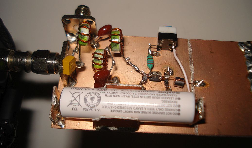
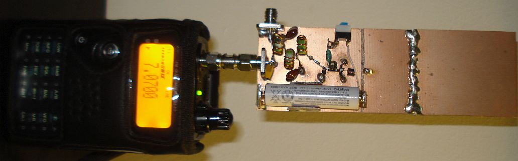
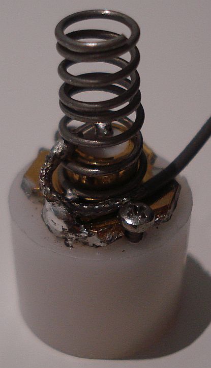
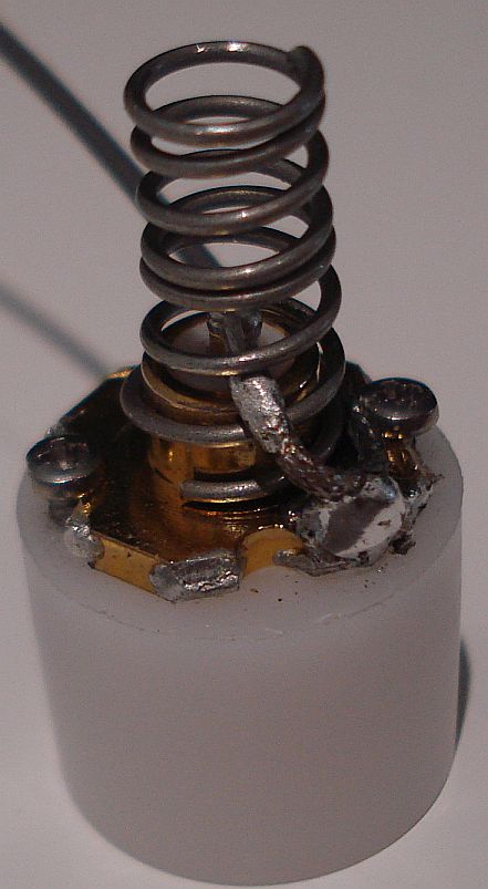
I have tested this configuration, using the prototype shown in the picture above and it works very well, as designed. HF DX HAM stations come loud when being outside, but do not expect good DX performance by any active antenna when being inside the house, as the man generated noise will almost always dominate the signals (noise is amplified as well by this antenna). However, stronger stations can be received from inside the house as well, in quiet locations. This is the case with MW stations as well. LW reception is still problematic, but this is not due to the fault of the active antenna but the radio itself. This handheld radio struggles to receive well DX LW stations because there is much interference from the internal signals of the radio into the LW band. In my country, there is no LW station, so I cannot speak about local LW receiving capability. However, when being outside, I could receive 2-3 DX LW stations with the active antenna, whereas when using the internal ferrite loop antenna I could not receive any of them, probably due to interference from the radio itself into the LW band.
With the capability of the radio to select through it's menu, between the internal ferrite loop antenna or an external antenna, it is now very fun to see how the different antennas behave on receiving the same signal. With my active antenna in place, you have added a third option and now you can select between three antennas. The internal ferrite loop antenna, the rubber or your long wire external antenna and my active antenna, by switching it's power switch to on. Sometimes you find that you need more amplification and if you are in a quiet location, the active antenna outer performs the internal ferrite loop. Some other times, the local interference is so much, that switching to the ferrite loop antenna and changing its direction, is better than the active antenna. This is also the case, with two stations from different locations, transmitting at the same frequency.
For the prototype, I used as an antenna, a copper clad PCB instead of a metal tube. The active antenna can be left on, while you receive or transmit at VHF/UHF, or it can be switched off, it does not really matter. Even at 5W of TX output power, there is no damage to the PGA-103+. So now, you can TX with your friends, and listen to your favorite HF stations at the same time, without having to switch off or remove the active antenna from the radio and without the need for a long shortwave external antenna. Truly handheld operation!
--- UPDATE 1 ---
Today I received
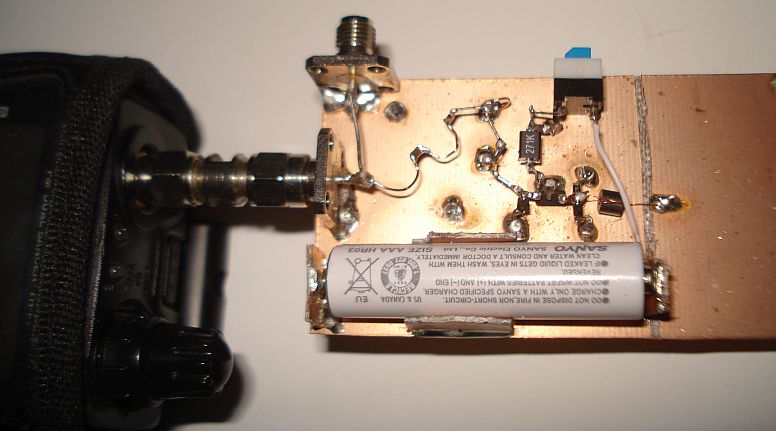
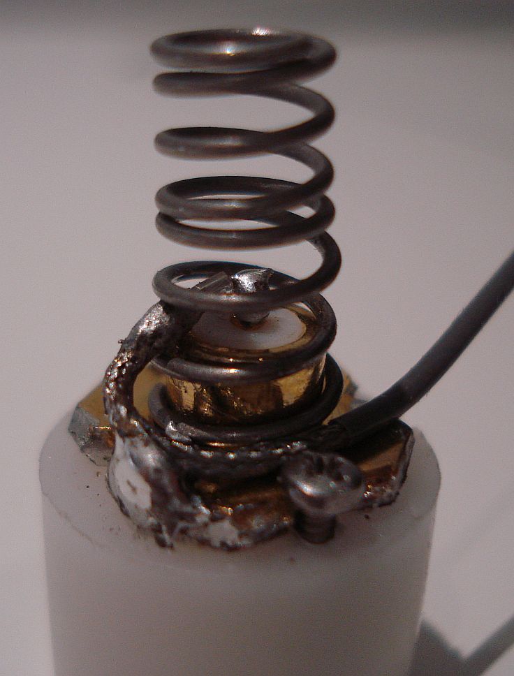
some tiny SMD inductors from a friend and I replaced them in the
circuit, as shown in the picture below. These were really tiny! I
tested the preamplifier, by transmitting at VHF and UHF at full power
(5W) for one full minute. No problems with the preamplifier and no
components were heated at all. This is an important step towards
minutarizing the overal preamplifier.
I have also changed the output capacitor from 100nF, to 470nF (schematic corrected), which I think gave better reception at LW. Now I can receive at least one LW station (French program) from inside the house.
--- UPDATE 2 ---
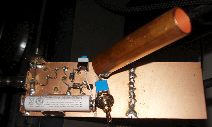
Today I wanted to
compare the performance of the copper sheet antenna element versus the
copper tube, both of equal area. If the performance is proven to be
equal or even better, this would be an important step towards the
minutarization of the active antenna. To compare the two antennas, I
have put a switch to immediately switch between them. Something
unexpected happened. The copper tube was a bit quieter than the copper
sheet, while both gave the same S-units. I have compared them at all HF
frequencies and with signals of different strengths and the results
confirm this.
--- UPDATE 3 ---
The
idea of the active antenna, was to be so small that it could be built
into a rubber duck structure, that sits just below the main antenna of
the radio. However, it is difficult to think of a practical way to
remove the battery from the preamplifier enclosure when it needs
charging. To overcome this, a suitable embedded charger has to be made.
Given the limited space, we do not have the luxury to embed a complex
charger into the antenna, so a very simple charger that does the
job just right for it's simplicity is presented here. The whole circuit is shown below.
|
|
|
|
 |
 |
|
|
|
|
|
|
|
|
|
|
|
|
|
|
|
|
|
|
1n4003 |
|
1n4003 |
 |
GND <-pin |
|
|
ON/ Charge |
|
470nF |
|
|
|
1.2V AAA |
750mAH Ni-MH LSD |
|
|
TX ant |
|
|
|
|
78M05 | |
 |
|
OUT <-pin |
|
 |
|
 |
|
|
|
|
RX ant |
|
|
100nH |
|
220nH |
|
1n4003 | |
100R 1W (50mA) |
|
|
270uH |
|
pga 103+ |
470nF |
|
|
|
4t FB43 -101 |
|
|
|
|
|
|
|
|
|
|
|
|
|
|
|
|
|
|
|
|
|
| in/out | |
100pF |
|
100pF |
|
100nH |
|
1uF |
|
|
1uF |
|
|
2x |
|
|
|
10k |
|
|
|
|
|
|
|
|
|
|
|
|
2x 1n4148 |
|
|
|
|
|
|
|
|
Note the components changes in the preamplifier. The charger consists of a 78M05 that is configured as a constant current source. The battery is shunted with two 1N4001 diodes in series. If the battery voltage is lower than the combined Vf of the diodes (~1.3v), all the current goes through the battery. As the battery voltage rises (roughly above 1.3v), the diodes start to conduct and divert the current to ground. The constant current maintains the charge rate and the diodes prevent over voltage. It isn't particularly efficient but it only uses a few components.
When
the switch is open (preamp off) the only drainage path for the battery
is through the series diodes, so when the battery voltage drops below
the combined Vf of the series diodes, the diodes will stop conducting
(apart from tiny leakage current) and nothing will further drain the
battery. Note that a fully charged battery may have a higher terminal
voltage than the combined Vf so current from a fully precharged battery
WOULD be drawn until the voltage dropped to a certain level, even if
the preamplifier is off. Also note that diodes do not have an abrupt
conduction voltage, their current gradually tails off below Vf so for a
short while, some (gradually fewer) current might flow. To avoid this,
one could
increase the clamping voltage to slightly higher than full battery
voltage, so as to ensure there is a safety margin against leakage while
not letting it go too high and possibly damage other things. However,
to simplify things, I prefer to keep the battery a bit undercharged.
The preamplifier
can work down to 0.6V anyway, so there is quite a lot of headroom.
Idealy, the preamplifier must be switched to off while charging, but it may work to the on position as well. Note that the output pin of the 78M05, is connected to the GND pin with a resistor. So the GND pin becomes the output of the constant current source, which means that the 78M05 GND pin is not connected to the real GND of the circuit. For that reason, a grounded copper PCB cannot be used as a heatsink anymore.
The 100R resistor, defines the charging current which, for safe charging,
must be close to 1/10 of the total capacity of the battery (750mAH),
thus 75mA. To change this current to your needs, all you do is
calculate the resistance to pass current equal to 1/10 of the total capacity of your battery. For example, if you use a this 5V regulator and want 75mA to flow, use R=V/I to get 66 Ohms.
The drawback to that arrangement is you drop a little over 5V in the
regulator so you need a minimum of say 7V above battery voltage for it
to work. it also dissipates some heat, W=V*I = 5 *0.075 = 0.375W in the
resistor and (supply voltage - 7 - battery voltage) * 0.075 in the
regulator. (about 0.3W from a 12V supply). Note that in
my circuit I finally decided to use a 100R resistor for a charging
current of 50mA. This is less than my battery 1/10th, but I did so as a
thought to keep things cooler and safer, despite the more charge time
required.
This low components charger is not automatic. In other words, it does not
indicate when the battery is fully charged or how much time has left
for the battery to be fully charged. However it prevents overcharging,
so you may leave it overnight or a few hours more and there will be no overcharging problems.
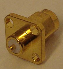
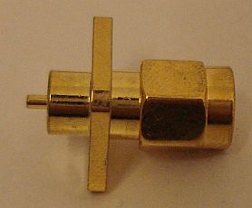
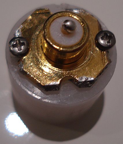
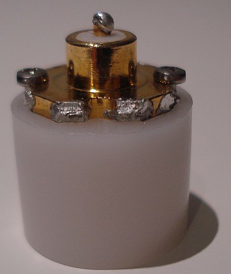
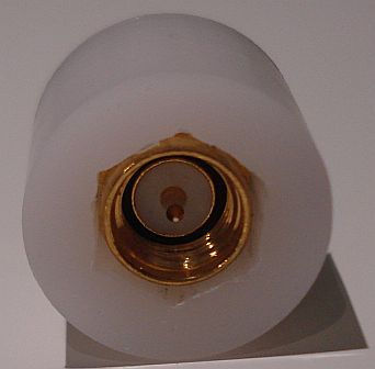
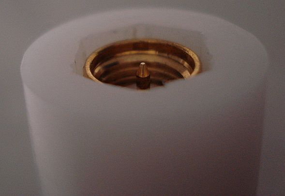
Because I wanted to make the active antenna splash-proof and because of the limited space, I did not want to use a separate power connector for charging the antenna. The input RF connector (the one that connects to the transceiver) is used for charging. The active antenna has to be removed from the transceiver in order to be charged. Do NOT try to charge the active antenna from the other connector (the one that connects to the V/U antenna side), because if the antenna is connected to the transceiver, you will apply power to the transceiver RF port, with unknown consequences. To prevent this and because the input and output RF connectors of the antenna are male and female respectively, I use a female connector onto the external charging transformer, which can only match the male port connector of the active antenna.
The same charging transformer that comes with the radio, is used to charge the active antenna as well. The extra power drawn by the charger is very small and can be handled by the transformer. Also, the active antenna charger circuit, already contains a 78M05, which can easily handle the excess voltage of the charging transformer. This way, I do not need to carry an extra transformer with me to charge the active antenna. Only a simple cable adaptor with appropriate connectors must be made, to charge both the transceiver and the active antenna at the same time.
--- UPDATE 4 ---
Since the electronic circuit is finished, I started thinking of the mechanical construction of the antenna. Size does matter as already said, and the antenna is to be made into a rubber duck like enclosure. Here are two preliminary designs that will be surely refined.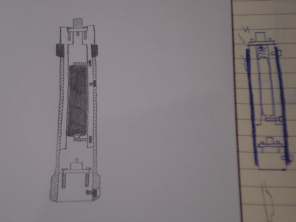
text
To be continued...