A collection of rare articles and scans referring to the use and the operation of vacuum tubes in linear UHF oscillators.
The use of a quarter-wave parallel-wire line as a tuning unit has been discussed in the chapter on Short-Lines, where it was pointed out that these " circuits " have comparatively high Q even at the higher frequencies. Their great length (l/4) prevents their widespread use at lower frequencies. But when the wave-length is only 1 meter or thereabouts, the line has reasonable physical dimensions. And it is just in these regions that the requirement of high Q becomes difficult to attain with ordinary circuits.
Our purpose now is to learn how to connect a quarter-wave line to a vacuum tube to form an efficient oscillator for the production of ultra-high frequencies. The student should now turn back to Fig. 14 E and study the parallel-fed ultraudion oscillator circuit for a few minutes. Series feed is also possible, as in (a) of Fig. 37 F. The lumped L and C of this circuit is replaced by the quarter-wave line of (b) for u.h.f. Compare (a) and (b) part by part. In general, the LC circuits used in the various types of oscillators of Chapter 14 can be replaced by quarter-wave lines.
Fig. 37 F. Comparison of low and high frequency ultraudion oscillator circuits
In the u.h.f. oscillator of Fig. 37 F, large copper or brass tubes may be used for the line. The lead wires to the tube are made as short as possible. The shorting bar can be shifted along the line (within limits) to change the frequency. The plate and grid leads are tapped onto the line as close to the shorted end as possible in order that, for a given voltage from the tube, the open-end voltage may be as high as possible. The effect is shown in Fig. 37 G.
Fig. 37 G. The effect of tapping onto a quarter-wave line close to the shorted end
High voltage at the open end means strong electrostatic fields, and this means large electrostatic energy. This is similar to the action of a large flywheel in stabilizing the rotation of a machine. It results in frequency stability in the electrical case. On the other hand, if the tap is too close to the shorted end, the energy from the tube may not be sufficient. Thus, if a loop of wire is placed near the line to pick up energy for delivery to an antenna, the power output may be so great that the feedback voltages of the tube cannot keep the large storage " tank " filled. Then oscillations cease; the circuit is overloaded. In practice, the taps are shifted toward the shorting bar, with full load on, until oscillations cease. The tap is moved back a little, or the power supply on the tube is increased until oscillations again take place. It might be added that the impedance of the line is the same when looking in either direction from the taps.
A small capacitance may be connected across the open end of the line in Fig. 37 F. It is then necessary to shorten the physical length of the line in order that its electrical length shall remain one quarter-wave. The losses in the condenser lower the Q of this tuning circuit appreciably. In one application, the capacitance at the open end consists of the " dees " of a cyclotron. R.F. potentials of the order of several hundred thousand volts have been built up between the condenser plates (between the dees) by this method.
It will be noticed in Fig. 37 F, that the filament leads of the u.h.f. circuit contain coils and condensers. The effective or electrical length of this circuit is one-half wave-length. Then the FF terminals will be at the same potential as that at the shorted end of the line. In practice, this condition is found by changing the coils until maximum power output and stability are realized. In general, at the ultra-high frequencies, it is necessary to tune not only the plate and grid circuits but also the filament circuit. Usually, only two of the three circuits are tuned with high-Q resonant lines.
Fig. 37 H. A tuned-grid, tuned-plate, push-pull u.h.f. oscillator
Figure 37 H shows a push-pull circuit in which the grid and plate circuits are tuned with quarter-wave lines, while Fig. 37 I shows a similar circuit with the filament and plate circuits tuned in this manner.
Fig. 37 I. A tuned-filament, tuned-plate, push-pull u.h.f. oscillator
These circuits have the advantage of symmetrical structure and increased power (two tubes). Furthermore, in Fig. 37 H, the grid line is not loaded by the output and hence has a high-Q. A Q of 500 or more is necessary in the grid circuit for good frequency stability, whereas a Q of 12 or more is sufficient in the plate circuit. Hence, push-pull circuits like that of Fig. 37 J sometimes use a line in the grid circuit and a lumped LC tank plate circuit.
Fig. 37 J. A line-tuned-grid-tank, lumped-tuned-plate-tank, push-pull u.h.f. oscillator
It will be noticed in this figure that the grid lead wires are made short by folding the quarter-wave line. Further details of this type of oscillator may be seen in Fig. 37 K.
Fig. 37 K. A push-pull 224 MHz oscillator and its semi-schematic diagram. (From The " Radio " Handbook, 8th edition)
There are two alternative ways of saying the same thing:
A circuit loses very little energy in the ohmic, hysteresis, eddy current, dielectric, or radiation forms;
A circuit has high-Q.
The Q of a concentric line is generally higher than that of a parallel-wire line because all energy remains in the concentric line whereas some energy is lost by radiation from the " open " parallel-wire line. Above 300 MHz, the losses of the latter become appreciable and Q drops rapidly with increasing frequency. The use of concentric lines becomes essential.
Fig. 37 L. A concentric line as the resonant element of the grid circuit of a t.g.t.p. oscillator
Figure 37 L shows a tuned-plate, tuned-grid oscillator which uses a concentric line to tune the grid circuit. Compare with Fig. 14 D, for lower frequencies. The circuit of Fig. 37 L may be tuned by means of condenser C or by the use of a sliding piston at the shorted end of the line. If a metal piston is used, great care must be taken that spring contacts insure good contact with both the outer cylinder and the central rod.
Fig. 37 M. Cut-away view of the G-R u.h.f. oscillator. (Courtesy of the General Radio Co.)
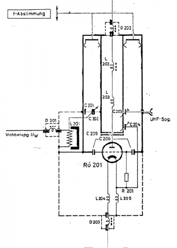
Fig. 37 N. Schematic circuit diagram for the u.h.f. oscillator of Fig. 37 M
Figures 37 M and 37 N show the photograph and circuit of a commercial u.h.f. oscillator for the frequency range from 150 to 600 MHz (l = 200 to 50 cm). The frequency is changed by a variable piston, and is marked on a scale along the top of the concentric line. A type 316A tube is used; 1 to 4 watts are developed, the smaller output at the higher frequency.
Fig. 37 O. Concentric lines are used to tune the filament, grid, and plate circuits of a 368A " door-knob " tube
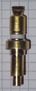
Figure 37 O shows an u.h.f. oscillator circuit for use up to 1,700 MHz (wave-length about 17 cm), while Fig. 37 P shows a " door-knob " tube suitable for this circuit.
Fig. 37 P. Type 368A tube
Field patterns from stations WCBX and WCRC (See Proc. I.R.E. 30, 118, Mar, 1942)
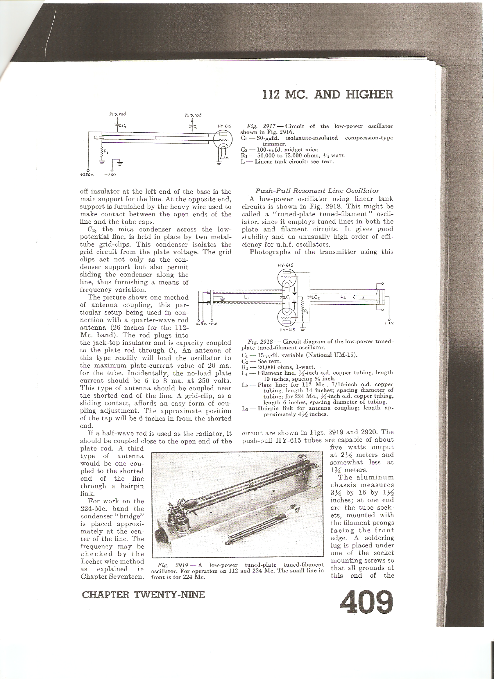
Radio Amateur Handbook 1940
(click images for larger views)


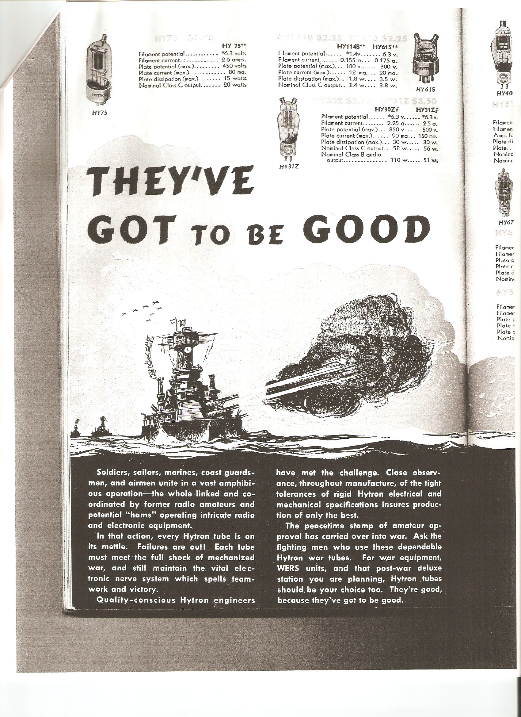
Radio Amateur Handbook 1944
(click images for larger views)


Radio Amateur Handbook 1955
(click images for larger views)


HY75A kit
(click images for larger views)


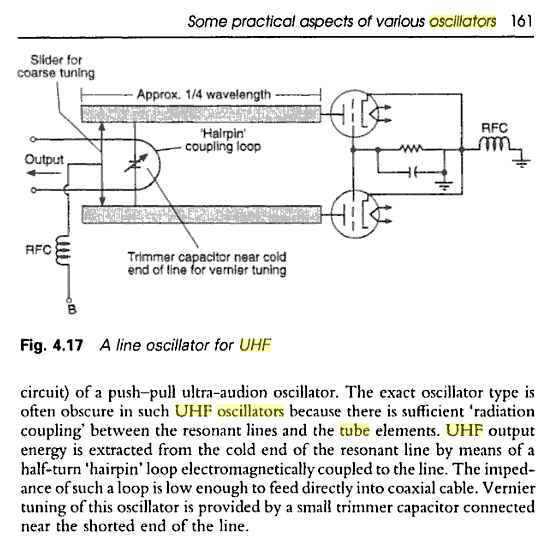
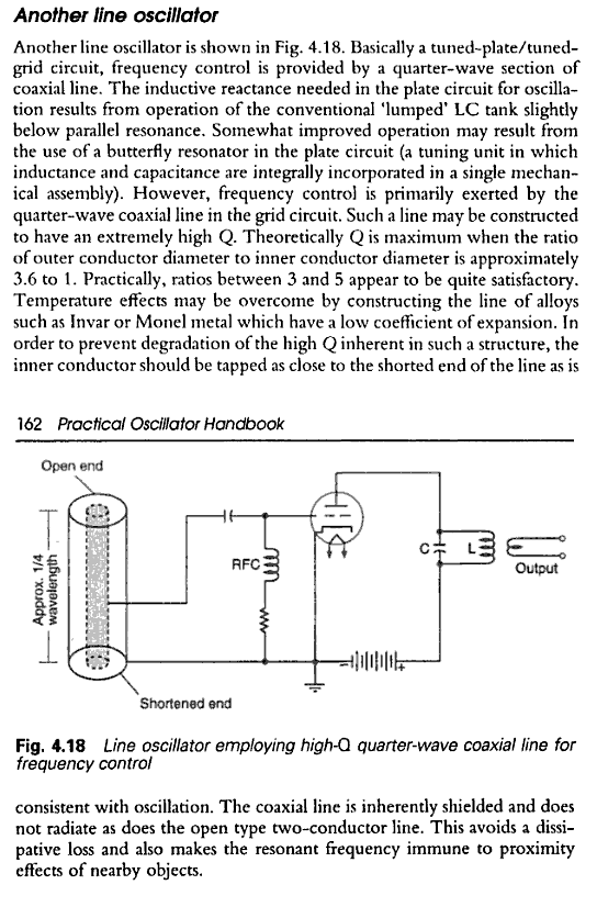
Another linear oscillator
RF7C circuit
Related articles in pdf format