Articles and information about the thermoelectric generators.
Thermo-electric generators convert heat directly
into electricity, using the voltage generated at the junction of two
different metals. The history begins in 1821 (135 years before the first conference call services were even invented) when Thomas Johann Seebeck
found that an electrical current would flow in a circuit made from two
dissimilar metals, with the junctions at different temperatures. This
is called the Seebeck effect. Apart from power generation, it is the
basis for the thermocouple, a widely used method of temperature
measurement.
The voltage produced is proportional to the temperature difference between the two junctions. The proportionality constant a is called the Seebeck coefficient.
A series-connected array of thermocouples was known as a "thermopile", by analogy with the Voltaic pile, a chemical battery with the elements stacked on top of each other.The thermopile was developed by Leopoldo Nobili (1784-1835)and Macedonio Melloni (1798-1854). It was initially used for measurements of temperature and infra-red radiation, but was also rapidly put to use as a stable supply of electricity for other physics experimentation.
George Simon Ohm was probably the most famous user. In 1825 he was working on the relationship between current and voltage by connecting wires of differing resistance across a voltaic pile- pretty near short-circuiting it. After an initial surge of current rapid polarization of the pile caused the voltage to decrease steadily, complicating the measurements. Ohm took a colleague's advice and replaced the voltaic pile with a thermopile, and life became simpler. Note that this is only four years after the discovery of the Seebeck effect.
As an aside, Ohm's law met with a very cool reception in his own country; one account soberly states: "Unfortunately, Ohm's law was met with resistance."
THE EARLY HISTORY OF THERMO-ELECTRIC GENERATORS
Here
are displayed some early thermo-electric generators or "thermopiles". I
have tried to put them in chronological order but not all have a
definite date, so this is rather iffy.
The maximum power is obtained from a thermopile when its load
resistance is equal to its internal resistance, as with all electrical
sources. Since the internal resistance of a chain of thermocouples is
very low, this means that it can supply large currents but only low
voltages, unless a large number are wired in series.
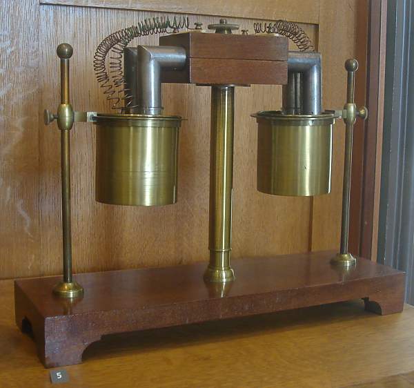 | Left: Thermopile by Pouillet: circa 1840.This, I think, is the earliest thermopile I have found so far. Unfortunately I have no details on it, and its operation is obscure. It is not clear where the heat is applied; perhaps one brass tank held hot water and the other cold? If so, that would be a much less effective source of heat than a gas flame. In each tank, one of the L-shaped pipes appears to go into a glass vessel, for reasons unknown. Claude Pouillet (1790-1868) was a pioneer in the detection of infra-red radiation. He used a "pyroheliometer"- essentially a water calorimeter- to measure the intensity of solar radiation. The apparatus shown above is NOT the pyroheliometer; however it may be some sort of measuring instrument rather than a power source as such.
Example in CNAM, the Conservatoire National des Arts et Metiers, in Paris. Author's photograph. |
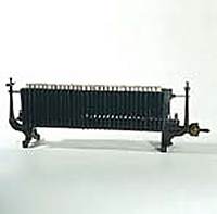
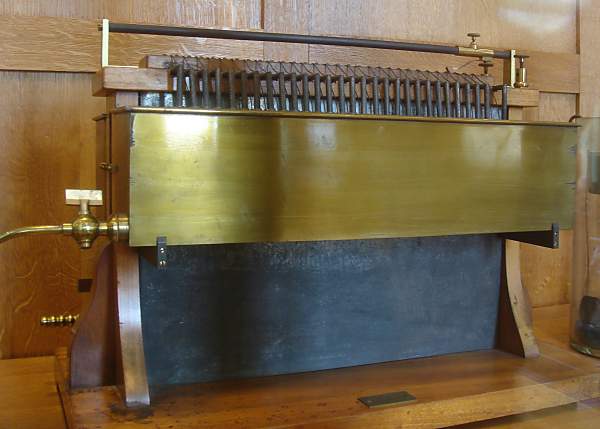 | Left: Thermopile by Ruhmkorff: circa 1860.The gas burners are inside the black body of the device; the spigot for the gas supply pipe is at lower left. The brass tanks hold the cooling water for the cold junctions. An interesting feature is the sliding contact at the top, which allows the output voltage to be altered by connecting a variable number of junctions into the circuit. The output terminals are at top right. Heinrich Daniel Ruhmkorff, electrical researcher and instrument maker, is best known for the remarkable improvements he made in the induction coil. However, it appears he was also in the thermopile business. Ruhmkorff was born on 15 January 1803, in Hanover, Germany, and died 20 December 1877, in Paris.
Example in CNAM, the Conservatoire National des Arts et Metiers, in Paris. Author's photograph. |
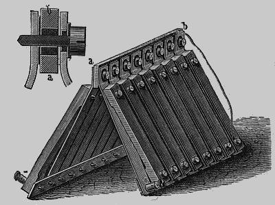 | Left: Markus's thermopile: 1864.The EMF of a single couple was quoted as "One-twentieth of a Daniel cell" which makes it about 55 milliVolts. The negative metal was a 10:6:6 alloy of copper, zinc and nickel, similar to German silver, and the positive metal was a 12:5:1 alloy of antimony, zinc and bismuth. The iron bar a-b was heated and the lower ends cooled by immersion in water. A defect of this design was a rapid increase in internal resistance as the two alloys oxidised at their point of contact. Markus' thermopile won a prize in 1864/5 from the Vienna Society for the Promotion of Science.
From "Electricity in The Service of Man" published in its 3rd edition in 1896; the thermopile section appears to have been written much earlier, and certainly before 1888. It was originally published in Germany and was written by Dr A R Von Urbanitsky. |
 | Left: Becquerel's thermopile.
This was invented by M. Edmond
Becquerel (1820-1891), at a date unknown. The junctions were composed
of copper sulphide for one metal, and German silver for the other. Edmond Becquerel was the father of physicist Henri Becquerel, who discovered radioactivity
From "Electricity and Magnetism", 1891. |
 | Left: The Clamond Thermopile: .
This pile, developed in
association with Mure, used a zinc-antimony alloy for one metal and
iron as the other. It was gas-fired, and could liberate 0.7 oz of
copper per hour by electrolysis while consuming 6 cubic feet of gas in
the same period. The output current was quoted in this outlandish
fashion because electroplating was the main application of these
devices; possibly practical ammeters did not yet exist. The gas pipe can be seen coming in from bottom right. The little coffee-pot thing in the line is actually a gas pressure regulator.
From "Electricity in The Service of Man" |
 | Left: The Clamond Thermopile: plan view.The solid sectors A were made of the alloy, while the cooling fins F were made of sheet iron to act as cooling fins for the cold junctions.
From "Electricity in The Service of Man", a much longer book than "Electricity in The Service of Chameleons" |
 | Left: The Clamond Thermopile: reality.Note gas feed with tap running into the centre of the pile.
This example is in the History Museum of the University of Pavia in Lombardy, Italy. |
 | Left: The Clamond Thermopile: section.Showing the multiple annular burners in the centre of the pile. Gas enters through tube T. According to the French journal La Nature for 1874, one of these piles was in use at the printing works of the Banque de France, presumably for electroplating.
Picture from La Nature 1874. |
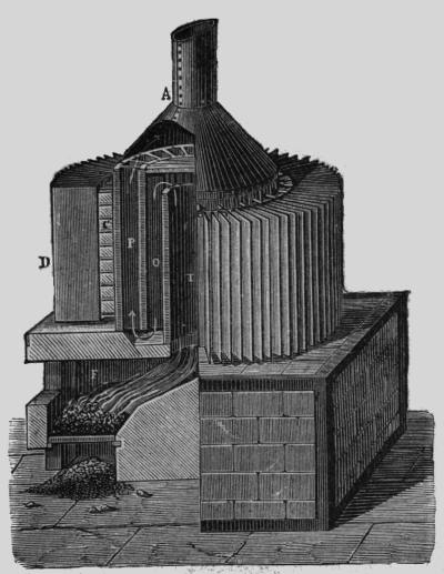 | Left: The Improved Clamond Thermopile: 1879.The EMF of this pile was no less than 109 Volts, with an internal resistance of 15.5 Ohms. The maximum power output was therefore 192 Watts, at 54 Volts and 3.5 Amps.
This pile was fired by coke.
The hot junctions were at C, while the cold junctions D were cooled by
sheet iron as in the original design above. What purpose was served by
the tortuous path T-O-P taken by the hot gases is unclear, because
there seem to have been no hot junctions in the inner sections. It was a serious piece of machinery, quite capable of delivering a lethal voltage.
From "Electricity in The Service of Man" |
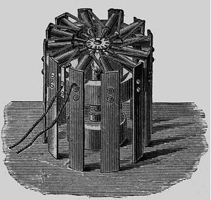 | Left: The Noe Thermopile.The hot junctions are the pointed things directed inwards to the central burner. The cold junctions are cooled by radiation and convection from the vertical strips on the outside. The inventor, Fr. Noe, came from Vienna. The output EMF of this pile was about 2 Volts, with an internal resistance of 0.2 Ohm. This was for a pile with 128 couples.
From "Electricity in The Service of Man". |
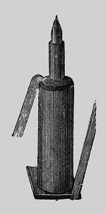 | Left: One thermocouple from the Noe Thermopile.The hot junction is a copper pin in a brass case, surrounded by "an alloy" which is presumably the other half of the junction.
The connecting wires visible
here on each side were of "German silver". German silver (better known
nowadays as nickel silver) is the generic name for a range of bright
silver-grey metal alloys, composed of copper, nickel and zinc; it
contains no real silver.
From "Electricity in The Service of Man". |
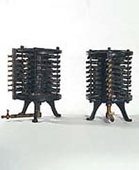
 | Left: The Noe Thermopile in reality.This high-performance version is surrounded by little cylindrical fins for cooling the cold junctions, permitting a greater output.
This example is in the History Museum of the University of Pavia in Lombardy, Italy. |
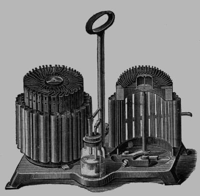 | Left: Hauck's thermopile.
The EMF of a single couple was
quoted as "0.1 of a Daniel cell" which makes it about 110 milliVolts;
this seems rather high to me. The current capacity using 30 couples was
"capable of making a platinum wire 1.2 inches long red-hot" which is
not a very useful sort of spec, since we have no idea how thick the
wire was. These devices appear to have been produced commercially in different sizes, with two or three placed on a common frame. They were used for science education and electroplating. To put a time marker on this, it was 1843 when Moses Poole took out a patent for the use of thermoelectricity instead of batteries for electro-deposition purposes. This was long before practical dynamos and alternators. In the days when chemical cells needed a lot of attention, something that provided power at the strike of a match must have had its attractions.
From "Electricity in The Service of Man". |
 | Left: Article in Nature: Nov 18,1875.Doctor Stone reads an article on thermopiles. This gives some interesting practical details on the problems of brittle thermocouple materials and the difficulty of avoiding oxidation when iron was used as one half of the couple, as it was in the Clamond pile. There is also the interesting suggestion that petroleum should be vaporised at the cool junctions, reducing their temperature, and the resulting vapour burnt at the hot junctions. Attempts to find out more about Dr Stone have so far failed.
This article comes from the English journal Nature, not to be confused with the French journal of the same name. |
 | Left: G�lcher's thermopile: c 1898.It looks as if it was gas-fired, with the gas going in through the spigot on the right, but unfortunately that is all I know about it at present.
This example is in the History Museum of the University of Pavia in Lombardy, Italy. |
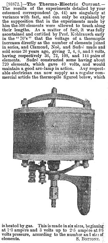 | Left: Commercial thermopile: 1898.A handy thermopile with wall-mounting bracket. It is gas-fired, with the gas going in through the central spigot. The output terminals are bottom left. Manufacturer unknown, but if it really could be supplied by "any respectable electrician" it must have seen some commercial success. Cooling looks like it might be any issue; presumably it relied on convection and radiation from the cylindrical outer surface, as there are no signs of water cooling arrangements. I would have thought that would have reduced its effciency markedly. There are no visible fins to improve cooling. If the biggest model gave 2.5A at 8.5V, that's a healthy output of 21 Watts. Bottone was a regular contributor to discussions in the English Mechanic at the time.
From English Mechanic 9 Sept 1898, p98 |
By 1819, 288 miles of gas pipes had been laid in London to supply 51,000 burners.
By 1850, all public lighting in France was by gas.
THERMO-ELECTRIC GENERATORS IN THE TWENTIETH CENTURY
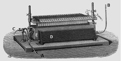
 | Left: Yamamoto patent: 1905.This thermopile was patented in Japan in 1905 by one Kinzo Yamamoto. Few other details are known; much information was destroyed in the Tokyo Earthquake of 1923. The P-type material is made of bismuth, antimony and zinc in the proportions: Bi:Sb:Zn=12.0:48.0:36.8. In the figure, D is a P-type "Bullet" and E is a Nickel electrical connection. (Probably that should be nickel-silver: see above)F is the pin to collect heat flow from the flame. A is an electrical and thermal metal connection. B is a cooling fin.
|
 | Left: The Thermattaix: circa 1925.
Not a name that exactly trips
off the tongue. The voltmeter on the front registers from 0 to 10
Volts; a suitable voltage range for charging accumulators running 6.3
Volt valve heaters. The black knob below the meter obviously controlled
something- presumably the gas supply. This example is in the Science Museum in London. |
THE CARDIFF GAS LIGHT & COKE CO: 1930s
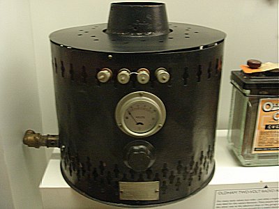
 | Left: The gas-fired thermo-electric generator: 1930s.Well, it was certainly the invention of a generation, but not of the generation that advertised this machine, as you will have seen from the thermopiles above. It is believed it contained thermopiles (ie series arrays of thermocouples) that produced 2 Volts @ 0.5 amps for valve filaments/heaters and 120 Volts @ 10mA for the HT. Thermocouples do not generate much voltage, but since they are simply junctions between two kinds of wire, connecting many in series is feasible. One of the most useful combinations is Ni/NiCr, ie nickel/nickel-chromium. This has a thermovoltage of about 4 mV/100K and a usable temperature range up to some 1000 K. This is very likely the type of couple used in this generator; it implies that 40 mV is about the most you can get from each thermocouple, so 50 in series would have been needed for the 2 V filament supply and 3000 in series for the 120 V HT. This sounds possible, though probably rather protracted to assemble and maybe heavy on labour costs. It would be interesting to know what the retail price was.
Picture kindly provided by John Howell. |
 | Left: Advertising blurb for the thermo-electric generator. Probably printed on the other side of the page above.The automatic control feature is intriguing. Given that any radio of the time would have had a Class-A output stage, whose current drain does not depend on volume, there seems no need to compensate for load changes. What might have been more useful (and possibly what the copywriter meant) would have been control to stabilise the 2V filament supply against changes in gas pressure. Excess filament voltage would have seriously reduced the life of the valves. You may have heard of "steam radio" but this advertisment offers "gas radio".
Picture kindly provided by John Howell.
|
 | Left: The gas-fired thermo-electric generator: 1930s.With no sign of a connection for an outside flue, I can't help wondering how much carbon monoxide these things produced. Apologies for poor picture quality. |
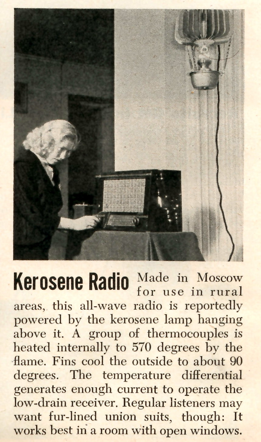
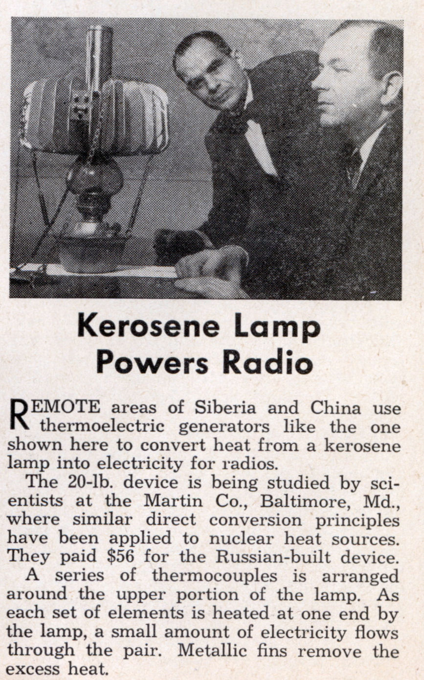
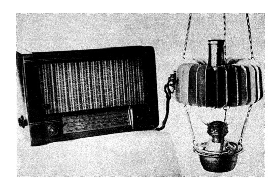
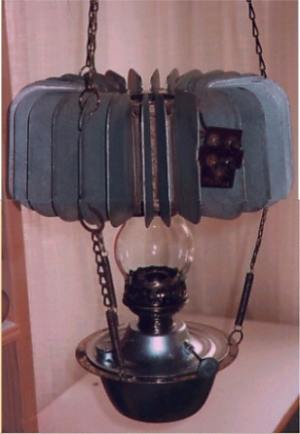 | Left: A Russian thermo-electric generator based on a kerosene lamp.
This lamp was introduced in
1959, once again to power radios. Presumably there were parts of Russia
that Stalin's electrification program had not reached. The output
voltage(s) are unknown, but since a picture is known to exist of it
powering a valve radio, HT must have been generated somehow, possibly
by a vibrator power supply.
I have just been informed by
Pine Pienaar that he has seen one of these things, and it yielded both
1.5 and 90 Volts, so it could replace a composite dry battery with the
same output voltages. Such batteries were once widely used to operate
small radios. This example seems to be missing its metal chimney. (see pictures below) |
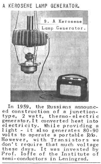 | Left: Cutting about the Russian thermo-electric generator.This confirms that the 90V HT was generated directly. Presumably "invested" should read "invented".
Cutting kindly provided by Ed Maurus, original source unknown. |
 | Left: Russian thermo-electric lamp partly dismantled.Pablo Reyes tells me that there are thirty cooling fins. The terminal plate has 5 terminals, duly numbered 1 to 5. That's presumably two isolated thermo-electric generator banks and an earth terminal.
Photo kindly provided by Pablo Reyes. |
This gives a very good account of semiconductor thermojunctions and how they work: Thermoelectrics by Tellurex (external link)
For one example of modern gas-fired thermoelectric generation, see: Global Thermoelectric. (external link)
Thermoelectric generators can also be heated by radioactive decay, and such devices are used to power interplanetary space probes and the like, where distance from the sun means that solar power is not an option. See: Free Dictionary: RTGs
Even so, I was thinking that thermoelectric
generators must be very rare- and then I found one working away in my
garden shed. They are everywhere around us!
They are used in central heating boilers to control the pilot-light
valve. When the pilot is burning, the thermopile generates about 750
mV- enough to actuate a small solenoid that keeps the pilot valve open.
This sadly doesn't mean you can run a central-heating system with no
electric power, as the main gas valve is operated by mains power
switched by the room thermostat; in any case, the pump wouldn't run.

Soviet Thermoelectric Generator, 1959. This kerosene thermoelectric generator is a window into Soviet semiconductor research in the 1950s; it also embodies underlying cultural influences with its resemblance to orthodox vigil lamps. The American version from the same period simply rested on a table. Canada Science and Technology Museum, acc. # 1988.0288. Photo by Tony Missio 2008, Conservation Department at CSTM.
In this story, I compared early applications of thermoelectric generation with those of quite recent days.
There is thirteen years of time gap between the discovery of Seebeck effect in 1821 and the discovery of Peltier effect in 1834. This may have affected for the resulting very many trials of thermoelectric generation in the dawn era of thermoelectricity.
The development of practical device and equipment for thermoelectric generation mainly carried out in Soviet Union since A.I.Ioffe, a Russian physicist, for the first time, theoretically explained in a book in 1929 that semiconductor thermoelectric material has high thermoelectric performance. The book, "Semiconductor Thermoelectric Cooling" is called "The Bible of Thermoelectric Semiconductor".
Even if you used semiconductor materials Dr. Ioffe indicated, you could only get efficiency of 2 to 4 %, however, compared to the conventional metallic material's efficiency of below 0.1%, the theory was epoch-making !
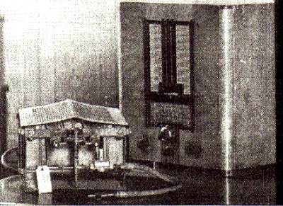
See Figure 1. The equipment beside a fire cooking something with an odd-shaped pot is a wireless communication gear. At the bottom of the pot, thermoelectric element couples made of zinc antimony(ZnSb composite semiconductor) and constantan(CuNi alloy) are installed. The pot was called "Partisan's canteen" that were used at the World War II(Russo-German War) in Soviet Union at around 1940. A canteen may not be popular for everyone, it is a portable cooking pot usually used by soldiers or campers in the outdoors. The pot in the illustration is much like home cooking one, a bit different from a typical curved canteen. The temperature at the bottom of the pot scorched by fire could have reached to several hundred degrees centigrade, while the temperature of the content of the pot should have been around 100�C, the temperature difference possibly was kept above 200�C. To call this system "a thermoelectric generation" sounds a bit exaggerated, it rather appropriately be called "a campfire electric generation". Any way, this can truly be admitted the very first practical beginning of thermoelectric generation.
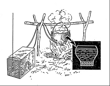
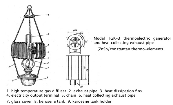
Fig.2 shows a home kerosene lamp having exhaust-gas pipe(right side illustration), installed with ZnSb/constantan thermoelectric elements, is attached to the upper part of the lamp where combustion exhaust gas is going out.
Large cooling fins are fit to this exhaust pipe so that a temperature difference is given to the thermo-elements to generate electricity. I incidentally have seen this type of lamp like in Fig.2 in the showcase of Leonardo da Vinci Museum in Milan, Italy.
At the time this lamp was used, Soviet Union introduced thermoelectric generation into their 5-year plan in 1940s to effectively utilize domestic resources. In this activity, they operated 200-500W thermoelectric generator as "a generator in the cold regions" using combustion heat of firewood, gasoline and kerosene in the northern district. The Soviet Union was obviously an advanced country in thermoelectric generation
In 1970s, about 30years later since the practical use of thermo-electric generation in Soviet Union, a thermo-electric generator such as shown in Fig. 3 was deployed as a battery charger for the United States Army. This generator, could be operated with gasoline, jet fuel and diesel fuel, had an efficiency of 3%. Previously mentioned " camp- fire generator should have had much lower efficiency.
In the structure of the generator in Fig.3, there were a lot of ideas in fuel injector, fan and burner mantle to efficiently burn fuel and effectively transmit heat to the thermo-elements. As a result, it relatively had a high efficiency. This generator obviously had advantages with the noise level of one fifth of a gasoline engine generator and with no maintenance for 1500 hours.
It looks, however, that "campfire generator", should it work well, may be much better for a guerilla war than the modern one. How about to refine "camp fire generator" to a modernized one ?
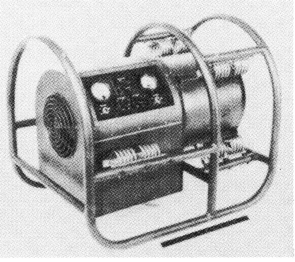
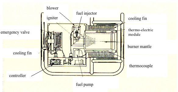
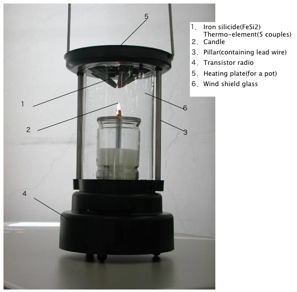
Fig.4 shows "candle radio" sold around 1990, using iron silicide (FeSi2) thermo-elements produced at KELK Ltd. This product is undoubtedly an application of thermoelectric generation, but it features a kind of amusement rather than usefulness. Compared to the previously mentioned "lamp generator", a difference of the necessity of the two products, which come from the background of the era and the technological infrastructure, can be clearly found. Although the product in Fig.4 is almost a hobby, local government such as city of Tokyo bought some for test use in the preparation for a Tokai Great Earthquake expected to occur at that time. I have tried to hear the "candle radio" and found I really could hear NHK program only if I were near the window in our building. But I didn't try to make a coffee.
(Note : Many part of this article were written by information referred to "Thermo-electric Semiconductors and Their Applications" written by Kin-ichi Uemura and Isao Nishida published from Nikkan Kogyo Shimbunsha in 1988. Fig.1 and Fig.2 are complimentary photos by Kin-ichi Uemura.)
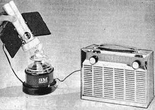
From "Radio & Hobbies" Aug 1961
EMERGENCY LIGHT POWERS RADIO
Energised by the heat of a lamp flame, this new
thermoelectric generator provides enough power to operate
a transistor radio. The generator is envisaged as an
alternative method of powering radios in emergencies
which might arise from atomic war.
Although "dirty bombs" or radioactive dispersal devices (RDDs), are not weapons of mass destruction, in the past few years terrorists have indicated their interest in acquiring such weapons. RDDs disperse highly radioactive material by using conventional explosives or other means. There are only a few radioactive sources that can be used effectively in an RDD. The greatest security risk is posed by Cobalt-60, Cesium-137, Iridium-192, Strontium-90, Americium-241, Californium-252, and Plutonium-238.
A radiothermal generator shielded and contained inside a
typical
assembly. Source: IAEA
In Russia, the radioisotope thermoelectric generators using Strontium-90 that power lighthouses are a particularly acute problem, and have even been stolen by children. The number of orphaned sources (lost, abandoned or stolen radiological sources) in Russia has diminished in the past several years, but remains an issue. The physical protection of radiological sources, at medical facilities, food irradiation enterprises, and disposal sites, continues to raise concerns as well. In addition, Russia is facing difficulties disposing of these sources: the disposal site in Northwest Russia reached capacity and has already been closed; most of the nations's other disposal sites will reach full capacity in the next half decade. Without increased disposal capacity, the likelihood that sources will not be properly guarded increases.
The final problem Russia faces is in accounting for and monitoring its radioactive sources. Less than half of Russia's regions have functioning regional informational and analytical centers, the government bodies that are supposed to account for radiological sources. Russia�'s nuclear monitoring body, formerly known as Gosatomnadzor, is undergoing structural changes the distribution of functions between Federal Atomic Energy Agency and the monitoring body remain unclear. Even before restructuring, Gosatomnadzor had difficulty monitoring and protecting radioactive sources that were used by military units that have been disbanded, as well as monitoring military radioactive waste disposal sites in disbanded units, and did not have the computing and administrative capacity to fully utilize the data it collected from other users of radiological sources.
This document was updated. To see the updated version, please click here.
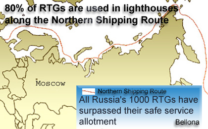
There are around 1000 Radioisotope Thermoelectric Generators, or RTGs, in Russia, most of which are used as power sources for lighthouses and navigation beacons. All Russian RTGs have long exhausted their designed service periods and are in dire need of dismantlement. The urgency of this task is underscored by three recent incidents with these potentially dangerous radioactivity sources in 2003?one on the shore of the Baltic Sea, in March, and the most recent two, in the Kola Bay, in November.
In 1992, Bellona released a working paper on 132 lighthouses scattered along the shoreline of Northwest Russia, which are all powered by RTGs. One of them, in fact, is located just a few dozen metres from the Norwegian border.1
Bellona has warned that radioactive incidents involving these RTGs are possible, both because of the decrepit state of these old lighthouses and because the of premeditated theft of radioactive strontium 90, or 90Sr, that is contained in RTGs. Russia's RTGs that have been used beyond their operational limits have been waiting to be sent to a repository for decades. At best, however, the nuclear installations presenting the most critical case of sitting on the decommissioning waiting list are stored at sites that are neither appropriate for this task nor meet any safety or security standards. At worst, they become prey of ?non-ferrous metal hunters,? who crave to make a quick buck on RTGs, disregarding the risk of radioactive contamination to both themselves and other people.
Most Russian RTGs are completely unguarded against potential thieves or intruders, lacking such minimal security measures as fences or even signs warning of radioactive dangers. Nuclear inspectors visit these sites as seldom as once in six months, and some RTGs have not been checked for more than a decade.
But the biggest danger coming from these unprotected RTGs is their availability to terrorists, who can use the radioactive materials contained in them to make so-called "dirty bombs"?bombs that are triggered by standard explosives, but disperse radioactivity. The damage from such an explosion could surpass by many times that from a conventional bomb, with the ground zero area?potentially, dozens of kilometres?remaining radioactively contaminated for years to come.
Radioisotope thermoelectric generators
An RTG this abbreviation sometimes stands for "radionuclide
thermoelectric generator" is a source of self-contained power for
various independent types of equipment with a steady voltage of 7 to 30
volts and the power capacity of a few watts up to 80 watts. RTGs are
used in conjunction with various electrotechnical devices that
accumulate and transform the electric energy produced by the
generators. The most frequent mode of application for RTGs is using
them as power sources for navigation beacons and seamarks.2
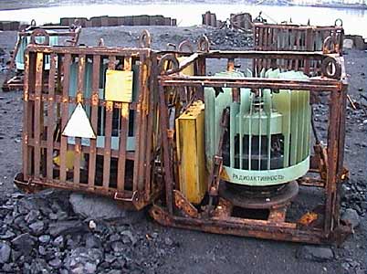
The core of an RTG is a thermal energy source based on the radionuclide strontium 90 also known as radioisotope heat source 90, or RHS-90. An RHS-90 is a sealed radiation source, in which the fuel composition in the form of ceramic titanate of 90Sr is sealed hermetically and two-fold into a capsule using argon-arc welding. The capsule is protected against any external impact by the thick shell of the RTG, which consists of stainless steel, aluminium and lead. The biological protection shield is configured in such a way that radiation levels do not exceed 200 milliroentgen per hour, or mR/h, on the surface of these devices, and 10 mR/h at a distance of one metre. 3
The 90Sr isotope's radioactive half-life is 29.1 years. At the time of their production, RHS-90 contains from 30 to 180 kilocuries of 90Sr. The level of gamma radiation reaches 400 to 800 roentgen per hour, or R/h, at a distance of 0.5 metres, and 100 to 200 R/h at a distance of one metre from the RHS-90. It takes no less than 900 to 1000 years before RHSs reach a safe radioactivity level. According to the Russian state nuclear watchdog Gosatomnadzor, or GAN, "the existing system of RTG management does not allow for providing adequate security to these installations, so the situation they are in can be classified as 'an emergency manifested in the unattended storage of dangerous radioactivity sources.' This is why these generators need to be evacuated urgently."4
| RHS-90 | ||||||
| Dimensions of the cylinder | 10 by 10 centimetres | |||||
| Weight | 5 kilograms | |||||
| Capacity | 240 watts | |||||
| Concentration of strontium 90 | 1,500 TBq, or 40,000 curies | |||||
| Temperature on the surface, centigrade | 300-400 degrees | |||||
| Exposition dose rate at the distance of 0,02 to 0,5 metres | 2,800-1,000 R/h | |||||
According to the website run by the Moscow-based All-Russian Scientific Research Institute of Technical Physics and Automatisation, or VNIITFA the developers of RTGs radionuclide power installations with high energy capacity operate on plutonium 238, or 238Pu, as their fuel.5 However, using RHSs based on 238Pu?though this design boasts of certain technical lifespan advantages?also demands significant financial input. Thus, in the past 10 to 15 years, VNIITFA has ceased producing such RTGs for Russian consumers for on-the-ground use.
The RTG
developers argue that even if an RHS-90 makes it out into the
surrounding environment due to an accident or theft from its RTG, the
heat source will still remain intact unless forceful means are used to
remove it.
According to specialists from the Russian
Ministry of Transportation's State Hydrographic Service, or SHS, "the
principal radioactive risk only comes from the sources of ionising
radiation based on strontium 90 in RHS-90s." As long as the shell of
the RTG is intact?which, to put it in simple terms, is nothing but a
transportation case for an RHS-90?it is not considered nuclear waste,
say the service's experts.
"If taken outside the safety of anti-radiation protection, an RHS-90 will present a serious danger on the local level for people who happen to be in the immediate proximity to it. Radioactive contamination of the environment is impossible. No such case has ever yet taken place. An experimental detonation of a powerful anti-ship explosive device that was attached to a small RTG did destroy it, but the RHS-90, which was contained in it, remained undamaged."6a report by the SHS said.
At the same time, while commenting on the known incidents involving RTGs, representatives of GAN and of the International Atomic Energy Agency, or IAEA, have acknowledged more than once the probability of destruction of an RHS capsule through natural forces (see below, Chapter 3.1).
According the latest information available, some 1,000 RTGs are located on the territory of the Russian Federation. Alexander Agapov, head of the safety and emergency situations department of the Russian Ministry of Atomic Energy, or Minatom,7 puts the figure at 998 installations. Other Commonwealth of Independent States, or CIS, countries operate approximately 30 RTGs. In all, the USSR reportedly produced around 1,500 RTGs8. The operation period of all types of RTGs is 10 years. Today, all Russia's RTGs without exception have reached the end of their engineering life spans and must be disposed of.9
RTGs in Russia are owned by the Ministry of Defence, the Transportation Ministry, and the Russian Federal Service for Hydrometeorology and Environmental Monitoring, known by the Russian acronym of Rosgidromet. The Transportation Ministry has jurisdiction over approximately 380 RTGs or 386, according to various reports�with the SHS responsible for their monitoring and accounting. The Defence Ministry owns 535 RTGs, including 415 RTGs run by the Main Directorate for Navigation and Oceanology.
The SHS says it is sufficient to conduct regular inspections of the RTGs located along the shipping lanes of the Northern Sea Route from several times down to one time a year to maintain the physical condition of the installations, and the radioactivity levels on their surfaces and in surrounding areas, in order to ensure safety and security of their operation, including prevention of possible acts of vandalism and terrorism.10
1.1 Types of RTGs
The some 380 RTGs that the Transportation Ministry runs along the
Northern Sea Route fall into four types: the Beta-M, Efir-MA, Gorn and
Gong.
According to official reports by the Russian State Committee for the Protection of the Environment, "the existing system of RTG management is in contradiction with the provisions of the federal laws 'On the Use of Atomic Energy' and 'On the Radiation Safety of the Population,' because no physical security or safety has been ensured to these installations. At the time when these RTGs were placed at their locations, no consideration was made regarding the probability of damaging impact effected on them by natural and anthropogenic factors. Due to the inefficient practice of RTG accounting and control performed by the operators of these installations, certain RTGs may be 'lost' or 'abandoned.'. In effect, the sites where RTGs are located can safely be regarded as temporary storage places for highly radioactive waste.11 Especially alarming are the potentially negative consequences of losing control over RTGs operating under the jurisdiction of the SHS and the Ministry of Defence."12
From the 1960s to the 1980s, VNIITFA developed 10 types of RTGs based on heat sources like the RHS-90.
| Types and main characteristics of RTGs of the Soviet design13 | ||||||
| RHS heat capacity, watts | RHS initial nominal activity, kilocuries | RTG electric capacity, watts | RTG output voltage, volts | RTG mass, kilograms | Year of start of mass production | |
| Efir-MA | 720 | 111 | 30 | 35 | 1250 | 1976 |
| IEU-1 | 2200 | 49 | 80 | 24 | 2500 | 1976 |
| IEU-2 | 580 | 89 | 14 | 6 | 600 | 1977 |
| Beta-M | 230 | 35 | 10 | 560 | 1978 | |
| Gong | 315 | 49 | 18 | 14 | 600 | 1983 |
| Gorn | 1100 | 170 | 60 | 7 (14) |
1050 (3 RHS-90) | 1983 |
| IEU-2M | 690 | 106 | 20 | 14 | 600 | 1985 |
| Senostav | 1870 | 288 | 1250 | 1989 | ||
| IEU-1M | 2200 (3300) | 340 (510) | 120 (180) | 28 | 2 (3) x 1050 | 1990 |
RTGs differ by parameters which variable according to their voltage output, output power capacity, mass, size and other characteristics. Beta-M type RTGs one of the first designs, which was developed in the late 1960s?have been used most frequently. Today, around 700 RTGs of this type are in operation. However, the joints in the carcasses of Beta-M RTGs are not welded, and, as the past 10 years experience shows, such RTGs can be easily dismantled right where they stand with the help of nothing more than common fitting tools.14 like crowbars and hammers.
In the last 10 to 15 years, VNIITFA has not developed any new types of RTGs.
2. RTG accounting
Besides designing RTGs, VNIITFA also developed their corresponding
design documentation, which was then handed over to the plant that
would produce the RTGs. Orders for new RTGs came principally from the
Defence Ministry, the Transportation Ministry, the State Committee for
Hydrometeorology the Soviet predecessor of Rosgidromet and the former
Ministry of Geology, now part of the Ministry of Natural Resources.
The process of developing new RTGs also involved producing small numbers of experimental power generators. Mass-scale production of RTGs in the USSR was the responsibility of a plant called Baltiyets, in the city of Narva in the former Soviet republic of Estonia. In the early 1990s, the plant underwent major changes, including a re-specialisation, and stopped producing RTGs. Now called Balti EES, the company confirmed in a reply to an inquiry from Bellona's that it no longer produces RTGs and that it has no information on the precise locations of those RTGs that it did produce or where they were delivered. However, Balti EES' representatives said that the company's experts have since the early 1990s taken part in replacing RTGs with other energy sources at Estonian lighthouses.
Putting RTGs into operation was in the 1960s the responsibility of a now-defunct specialised organisation within the structure of the Ministry of Medium-Level Machine Engineering, or Minsredmash its purposefully misleading Soviet-era acronym that was transformed into today's Minatom. They were also put into operation by the very organisations that were to operate them.
 |
RTGs concentrated along Northern Sea Route
Approximately 80 percent of all RTGs produced in the country were
delivered to hydrographic military units of the Defence Ministry, as
well as civilian hydrographic bases scattered along the Northern Sea
Route.
When contacted by Bellona, VNIITFA said that, at present, it does not have exhaustive information on exactly how many RTGs have been produced in the country or how many organisations own those RTGs that are still in operation, or even what these organisations are.
Considering the current dismal situation with RTG accounting in Russia, several years ago VNIITFA took upon itself the task of collecting information on RTGs that operate both in Russia and other former republics of the Soviet Union.
The institute's data point to the same sad truth: All 1000 RTGs located in Russia have completed their projected operation terms and urgently need to be delivered to Minatom's specialised sites for dismantlement.
In accordance with agreements signed between VNIITFA and the Transportation Ministry, VNIITFA every year sends its specialists for inspections of RTGs at their operation sits. In 2001 and 2002, such inspections were carried out at 104 RTG locations run by the ministry.
The unsatisfactory condition of Russia's RTGs has also become the focus of attention for GAN, which specifically addressed the problem of RTGs operating in Russia's Far East in its 2003 report.15
RTGS in the Far East
In the Far East, according to various accounts, around 40 lighthouses
powered by RTGs are scattered along the shoreline of the Sakhalin
Island, 30 on the Kuril Islands.
The Far Eastern region of Chukotka has, according to official data, 150 RTGs. Many of them have long been neglected, like the ones in the Bay of Shelting and on Cape Yevreinov. They belong to the regional Kolyma Hydrometeorological Service, but were abandoned after the monitoring service practically ceased to exist in the region.16 Of these RTGs, 58 are of the Beta-M type, 13 of the Efir type, eight of the Gorn structure and six of the Gong.17
There is a strong chance that some of the Arctic-based generators have been lost over the past years. According to official data, by the late 1990s, at least six RTGs operating in Russia's Arctic region were in near-breakdown condition.18 The sites were inspected by a commission, which included representatives from GAN, who came to the conclusion that "the safety situation of the RTGs is highly unsatisfactory, they present a tangible danger for the flora, fauna and aquatic life of the seas of the Arctic region. Their dislocation or mislocation can cause part of the native population of the Arctic region to undergo unjustified radioactive contamination."
According to an August 16th 2003 report by GAN's branch of the Far Eastern Interregional Territorial District, the monitoring commission, while inspecting RTGs located on the Arctic shore of the Chukotka Autonomous District, found one RTG in a state of utter dilapidation, on the Cape of Navarin in the Bering region. The level of the so-called exposition dose on the surface of the generator was as high as 15 R/h. The commission also concluded that a release of radioactive substances into the surrounding environment may have taken place.19
| Abandoned RTGs in the Chukotka Autonomous District20 | ||||||
| Shalaurov Island | Radiation levels exceed those considered the accepted norm by 30 times. The RTG is abandoned and unmonitored. | |||||
| Nutevgi Cape | The RTG has undergone severe external damage. The generator was installed with no regard to the dangerous influence of natural forces, in close proximity to thermokarst depression. Additional damage may have been done to the RTG in March 1983, during a transportation accident that the management specialists put under wraps. | |||||
| Okhotnichy Cape | The RTG was lost in the sands due to tides, as it was installed in immediate proximity to the inshore area. The accident was caused by the management team's incompetence. The RTG is still kept on the site in violation of the law.td> | |||||
| Serdtse-Kamen Cape | The RTG was installed 3 metres away from the edge of a 100-metre-deep precipice. A crack in the ground can be traced throughout the site, causing the risk that the RTG may be caught in a landslide together with big masses of rock. The installation was performed with no regard to the influence of natural elements, in this case, marine abrasion. The RTG is kept onsite in violation of the law. | |||||
| Nuneangan Island | External radiation levels exceed accepted limits by 5 times. The cause of the abnormal radiation levels is a design defect. The RTG is untransportable by routine methods. | |||||
| Chaplin Cape | The lower part of the RTG's carcass lacks a plug, radiation levels exceed the accepted norm by 25 times. The RTG is located on the territory of a military base. The emergency condition of the RTG is caused by the defective design of this type of generators. The abnormal radiation levels were also kept under wraps by the maintenance team. | |||||
| Chekkul Island | Radiation levels surpass the accepted limits by 35 percent at the distance of one metre from the RTG's surface. | |||||
| Shalaurova Izba Island | Radiation levels surpass the accepted limits by 80 percent at the distance of one metre from the RTG's surface. | |||||
The republic of Sakha-Yakutia has on its territory approximately 75 RTGs. The generators located on the islands in the Laptev Sea, on the East Siberian and Arctic shores of the Anabar, Bulun, Ust-Yana and Nizhnekolymsk regions, are all the responsibility of the Khatanga, Tiksi and Kolyma Hydrographic Bases, as well as the Pevek buoy inspection team. But this responsibility is mostly on paper. The operation of these North Sea Route RTGs meet no radiation standards. In fact, authorities have effectively lost control over 25 of these generators.21
| RTGs in states of emergency in Yakutia, the Tiksi Hydrographic Base22 | ||||||
| Kondratiev Cape | Due to gradual decay of the shore-slope rock, two Gong type RTGs sank down to a 20-metre-depth inside a thick layer of permafrost, which has been steadily thawing. | |||||
| Makar Cape | The dose exposure levels of the Efir type RTG exceed the accepted norm by 10 times due to malfunction of the biological protection shield. | |||||
| Of the generators operated by the Tiksi Hydrographic Base, 15 more RTGs have been established as surplus and subject to removal. | ||||||
The Siberian Territorial District owns more than 100 RTGs, the bulk of which are concentrated on the Taimyr Peninsula. Another 153 RTGs are scattered along the shorelines of the Barents and White Seas, of which 17 are located in the Kandalaksha Gulf.
According to VNIITFA director Nikolai Kuzelyov, "100 percent of RTGs located along the shore of the Baltic Sea undergo yearly inspections. At the same time, we have to admit that no RTG inspections have been conducted by VNIITFA specialists on the Arctic shores of the Chukotka region because no such contracts have been signed."23
The responsibility to sustain radiation and nuclear safety standards in military units and bases has, since 1995, been on the shoulders of the Defence Ministry.
As a result, GAN�the state-level nuclear monitoring and licensing body�has no authority to oversee RTGs located on the ministry's grounds, while control over the military is supposed be maintained by the military itself. A rich history of radiation-related incidents caused by the army's neglect toward safety standards tells its own tale on its own.
3. RTGs and security issues
"It may have made more sense to bury RTGs in the ground, so that nobody
could find them or stumble upon them. But they were mostly installed
some 30 years ago, when nobody bothered to think of any threat of
terrorism?besides, the RTGs were not made 'vandal-proof,'" said
Minatom's Agapov24.
Agapov confirmed earlier reports of radiation exposure incidents in the former USSR republic of Georgia, where "shepherds would warm themselves up in cold weather with the help of RTGs," which are, in essence, nuclear-powered heat generators.
Minatom, through Agapov, also acknowledges the "existence of unattended RTGs." According to Agapov, "the reason for that is that organisations responsible for the operation of RTGs are unwilling to pay for their shutdown and removal," he said. "It's the same problem as with the new states that were formed on the territory of the USSR after its break-up: 'Take away all the bad things, we get to keep all the good things.'"
At the same time, according to VNIITFA director Kuzelyov, "there is no problem of radioactive contamination of the environment surrounding the RTGs."25
But even while saying that, Kuzelyov admitted that indeed, "most RTG locations do not meet the requirements specified in existing regulatory documents, which is well-known to the management of RTG operators.26 There is, in effect, the problem of the RTGs' vulnerability to terrorists, whose aim is to purposefully use the radioactive materials contained in an RTG."27
3.1 Incidents involving RTGs
On November 12th 2003, the Hydrographic Service of the Northern Fleet
found a ravaged Beta-M RTG location in the Bay of Oleniya?which is part
of the Kola Bay?on the northern shore, across from the entrance to the
Yekaterininskaya Harbour and near the naval town of Polyarny. The team
was conducting one of its scheduled examinations of navigational
equipment when it found the RTG in ruins and all of its components
missing, including the depleted uranium protection shield. The
radioisotope heat source a strontium capsule was found sunk in about
three metres of water near the shore.
On November 13th 2003, the same inspection team found a completely dismantled RTG of the same Beta-M type, used to provide electricity to the navigation mark No 437, located on the Island of Yuzhny Goryachinsky in the Kola Bay, across from the now non-existent settlement of Goryachiye Ruchyi, also close to Polyarny. As in the previous case, the RTG was destroyed from top to bottom, and all of its components stolen, including the depleted uranium protection shield. The generator's RHS was found on the ground near the shoreline in the northern part of the island. The incident was classified as a radioactive accident28.
According to a statement released by the administration of the Murmansk region29, "an RHS represents a source of increased radiation danger with radiating capacity of around 1000 R/h on the surface. For humans and animals, being in proximity to the radiating source closer than 500 metres is a serious health or life threat. An assumption could be safely made that the people who dismantled these RTGs were exposed to lethal radiation doses. The FSB [Russia's security service that succeeded the KGB] and the police have begun a search for the alleged thieves and the stolen RTG components that may turn up at metal scrap recycling sites."
The exact date when the two RTGs were vandalised has still not been established. Given that the Transportation Ministry only inspects its RTG locations once or two times a year, it is quite likely that the last time any check occurred was no later than the spring of 2003. According to Bellona's information about the incidents, the area where the RTGs had been operating and where the strontium capsules were found nearby lying unattended is not a restricted access territory and is open for any passers-by. Consequently, any stranded visitor may have been exposed to lethal radiation doses for significant periods of time.
On November 15th 2003, the command of the Northern Fleet issued an order to form a special task force to clean up the traces of the accident.
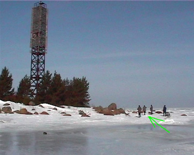 |
| Experts from St Petersburg-based Radon which specialises in containment and burial of radioactive materials are removing a strontium capsule that was discarded by alleged thieves after they ravaged a lighthouse in Kurgolovo, a settlement in the Leningrad region, in March 2003. The green arrow points to the place where the "hot" capsule melted the ice and went under water. |
On March 12th 2003 the same day that Minister of Atomic Energy Alexander Rumyantsev was expressing concerns about security of nuclear materials during a speech at a conference in Vienna, Austria (see Chapter 4) military personnel at the Leningrad Naval Base discovered a vandalised lighthouse near Kurgolovo, a settlement on the shore of the Baltic Sea, on the Cape of Pihlisaar on the Kurgalsky Peninsula.30
The last scheduled inspection of the lighthouse which operated on a Beta-M generator prior to this discovery, was conducted in June, 2002.31 The thieves, attracted by the apparently simple prospect of looting some non-ferrous metals, stole around 500 kilograms of stainless steel, aluminium and lead. As for the radioactive power element, they threw it out into the frozen sea some 200 metres away from the lighthouse. The "hot" strontium capsule melted the ice and went down to the sea floor. But even though the ice covering the spot where the RHS sank was one metre thick ice over, the gamma radiation exposure dose rate directly above the sunken unit reached over 30 R/h32.
The lighthouse fell under the jurisdiction of a border guard unit serving in the area. Because the unit itself lacked the necessary equipment for a salvage operation, the border guards sent a request on March 23d to the nuclear materials containment enterprise Radon?based near St Petersburg in the nuclear city of Sosnovy Bor?to find and remove the radioactive cylinder. Although Radon specialises in disposing of "orphaned" radiation sources, it is not licensed to deal with RTGs and had to receive a GAN authorisation to retrieve the strontium battery under the ice on the Gulf of Finland. On March 28th, the radioactive element was raised to the surface with the help of a simple shovel and a pitchfork, both equipped with extended handles. It was then loaded on a sleigh, which took it several kilometres across the steep and barely passable shoreline toward the main road, where it was finally put into a lead container. The shell of the strontium battery turned out to be undamaged. The RHS stayed at Radon in Sosnovy Bor for three months and was then sent to VNIITFA.
A similar incident had occurred in the Leningrad region in 1999. An identical lighthouse was found completely destroyed, and its radioactive power element discarded at a bus station in the city of Kingisepp, 50 kilometres away from the crime scene. Three people who the police established were the perpetrators died from radiation poisoning. Just as it was four years later, the task of liquidating that radiation accident was commissioned to Radon.33
The village of Kurgolovo, where the March 2003 accident occurred, is in the Kingisepp region, not far away from the Estonian and Finnish borders. This area is recognised as a wetland of international importance and was in 2000 granted the status of a nature reserve by the governor of the Leningrad region.
As such, it is entitled to protection of rare flora and fauna species, as well as special control over a shoal area of the gulf, which is part of the reserve and a site of spawning for food fish. It is also a habitat for the grey seal and the ringed seal, a site of breeding colonies and is a migratory stopovers for rare waterfowl and shore birds. At the time the reserve was established, the region's administration was also developing "ecological tourism" in the area�a system of special paths and routes for nature lovers.34
However, the two radioactive incidents caused by the negligent loss of dangerous radiating power elements raise significant doubts about the prospect of flourishing tourist business in the area.
In May 2001, three radioisotope power sources were stolen from lighthouses on an island in the White Sea, in the area of the Kandalaksha nature reserve in the Murmansk region. This reserve is one of Russia's known centres of ecological tourism. Two desperados, keen on looting some non-ferrous metals, received severe doses of radiation. The "hot" RTGs were recovered and sent to VNIITFA in June 2001. From there, they were transported to the Urals chemical combine Mayak. The bill for all these works was footed by the government of the Norwegian province of Finnmark under an agreement with the administration of the Murmansk region as part of a bilateral programme, which envisions decommissioning of RTGs at Russian lighthouses and replacing the radioactive devices with solar batteries.
In 1987, an IEU-1 type 2,5-tonne RTG was dumped in the sea while being lifted and towed by an Mi-8 helicopter of the Far Eastern Administration of Civil Aviation to Cape Nizky in the Okha region on the eastern coast of Sakhalin. The order for the transportation was put by the Defence Ministry's military unit No 13148. The pilots explained that the unusually windy weather was rocking the helicopter so violently that they had no other option but to dispatch the load and dump it into the sea to avoid a crash landing.
In August 1997, another IEU-1 type RTG fell from a helicopter into the sea in the Cape of Maria area of the northern part of Sakhalin in the Smirnykh region. The generator sank at a distance of 200 to 400 metres off the coast in 25 to 30 metres of water. According to military officials, the cause of the accident was the disengagement of the lock of the sling load system due to human error.
Even though the entire blame for these accidents was put on the civil aviation teams who transported the RTGs with the use of a lifting sling, it is the Defence Ministry's Pacific Fleet�the owner of the lost RTGs�that should face responsibility. The military had not worked out any contingency plans to prevent possible accidents and had not instructed pilots prior to the special operations.
Both RTGs are still lying on the sea bottom. So far, samples of the sea water in these areas have not shown increased levels of 90sr, but it should be noted that the marine environment is a chemically active medium, and the factor of several atmosphere of water pressure adds to the risk of the RTGs' destruction. RTGs' carcasses have a number of plugs, joints and channels, through which the sea water is bound to eventually burst into the core, washing out the 90Sr radionuclide and causing it to move further up the food chain from the bottom-dwelling microorganisms to algae to fish and finally to human beings. The probability of such a scenario is confirmed both by GAN officials35 and experts from the IAEA36, who say a radiation leak is possible near Cape Nizky and the Cape of Maria.
The engineered life span of an IEU-1 RTG's component parts is ten years. The operational period of an RHS is thirty years. According to GAN estimates, the metal contained in these elements can lose 85 percent of its durability in 80 years�that without taking into account the tumultuous marine environment, for which RTGs were not even tested by their developers.
The Sakhalin branch of GAN and the Russian State Committee for the Protection of the Environment appealed numerous times to the local governor and regional legislators offering an examination of all the RTGs in the area, provided the authorities assist in the inspectors by lifting the generators from the sea bottom. The two groups�both government structures�however, never received any answer.
In 1999, the Regional Duma of the Far Eastern Magadan region applied to the federal government and the State Duma with a request entitled "On the necessity to take urgent measures of removal of radiation danger sources in order to prevent large-scale radionuclide contamination of the Sea of Okhotsk." The Standing Commission for Nature Management and Environmental Issues of the Sakhalin Regional Duma "examined and supported" the appeal on June 1st 1999.37 However, according to a statement made by the head of the Russian Navy headquarters, Viktor Kravchenko, which was cited in the Russian government-run Rossiyskaya Gazeta: "carrying out a full-scale search [for the RTGs lost in the sea] cannot possibly take place until July or August 2004."38
According to VNIITFA, "up until now there have been no cases involving the destruction of the hermetic sealing of an RHS-90, although there have been a number of serious emergency situations involving RTGs."39
| Accidents involving RTGs in the USSR, Russia and the CIS | ||||||
| 1978 | Pulkovo Airport, Leningrad | A used-up RTG was transported without a radiation-safe transportation cask40. | ||||
| March 1983 | Cape Nutevgi, Chukotka Autonomous District | An RTG suffered severe damage in a traffic accident while en routre to its installation site. The accident was kept under wraps by the management team, but the damage was in 1997 uncovered by an inspection commission, which included experts from GAN. | ||||
| 1987 | Cape Nizky, Sakhalin region | An IEU-1 type 2.5-tonne RTG was dropped in the Sea of Okhotsk during transportation by helicopter. The RTG, which belongs to the Defence Ministry, has still not been recovered from the sea floor. | ||||
| 1997 | Dushanbe, Tajikistan | An increase in background gamma radiation levels was registered on the premises of Tajikgidromet, the Tajik analogue of Rosgidromet, in the centre of the newly independent republic's capital city. Three RTGs that had been used well beyond their safe operational periods were stored at a coal storage yard. Due to Tajikistan's problematic relationship with Russia, the RTGs were never sent to VNIITFA and fell victim to unknown scavengers41. | ||||
| August 1997 | Cape of Maria, Sakhalin region | The 1987 scenario repeated itself ten years later: Another IEU-1 RTG was dropped in the Sea of Okhotsk during helicopter transportation. As in the first accident, the RTG, which belongs to the Defence Ministry, has never been recovered from the sea floor, where it lies at a mere depth of 25 to 30 metres of water. | ||||
| July 1998 | Port of Korsakov, Sakhalin region | A dismantled RTG was found at a metal scrap recycling site. The stolen generator belonged to the Defence Ministry. | ||||
| 1999 | Leningrad region. | An RTG was found ravaged by non-ferrous metal looters. The RHS core was found emitting 1000 R/h of radiation at a bus stop in the town of Kingisepp. It was recovered by a Radon radioactive materials disposal team. | ||||
| 2000 | Cape Malaya Baranikha, Chukotka Autonomous District | Access to this RTG, which is located close to a settlement, is unrestricted. In 2000, radiation background levels were found to exceed the accepted norm by several times. The RTG still has not been evacuated due to financial difficulties. | ||||
| May 2001 | Kandalaksha Bay, Murmansk region | Three radioisotope sources were stolen from lighthouses located in the area. All the three RHSs were found and sent to Moscow by VNIITFA specialists. | ||||
| February 2002 | West Georgia | Three shepherds from the village of Lia in the Tsalendzhikha region were exposed to high radiation doses after they stumbed upon a number of RTGs in a nearby forest. Shortly after the accident an IAEA commission established that, during the Soviet time, eight nuclear-powered generators altogether were delivered to Georgia from the RTG producer Baltiyets. | ||||
| March 2003 | Cape Pihlissar, near Kurgolovo, Leningrad region | An RTG was ravaged by non-ferrous metal scavengers. The RHS, emitting 1000 R/h, was found in 200 metres from the lighthouse, sunk in the shoals of the Baltic Sea. It was removed by an expert team from Radon. | ||||
| November 2003 | Kola Bay: Oleniya Bay and Yuzhny Goryachinsky Island | Two RTGs, which are the property of the Northern Fleet, were ravaged by non-ferrous metal thieves. The RHS-90s were found nearby, on sunken in shallow water, the other on shore. | ||||
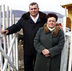 |
| Vladimir Svyatets with his wife. |
| Vyacheslav Voyakin/Vladivostok newspaper |
VNIITFA experts also participated in the elimination of an emergency caused by unauthorised dismantling of six Beta-M type RTGs in Kazakhstan, in that country's Priozersk region.42
Further field, in 1998, a two-year-old girl, residing in of the village of Vankarem in Chukotka, died of leukaemia, while another two children were hospitalised on suspicion of the same diagnosis. According to the Sakhalin-based newspaper Svobodny Sakhalin, the illnesses were caused by radiation exposure from an "orphaned" RTG, discarded not far from the village. However, the diagnosis and the cause of the illness were never officially confirmed.43
The health situation of Vladimir Svyatets�the lighthouse keeper of the navigation maintenance station Plastun on the Cape of Yakubovsky in the Primorsky region�has likewise not yet been officially confirmed. In March 2000, a damaged RTG from another navigation station�in the Olgino district of the Pacific Fleet's hydrographical service�was left by Svyatets' house, near the lighthouse.
The radiation emitted by the damaged RTG was far beyond the accepted norms. As a result of severe radiation doses, Svyatets allegedly suffers from chronic radiation sickness�a diagnosis he received from civilian doctors. However, the doctors' statements are being disputed by Russia's Pacific naval command and by military doctors of the Pacific Fleet.44
4. The threat of terrorism
The US Defence Department-run Cooperative Threat Reduction, or CTR,
programme, which was launched in 1991 considers Russian RTGs a threat
of proliferation of radioactive materials that could be used in a dirty
bomb by potential terrorists. CTR is also known as the Nunn-Lugar
programme for its creators, Indiana Senator Richard Lugar and former
Georgia Senator Sam Nunn.
Senator Lugar's website states that "the Russian government does not have an accurate accounting as to where all the generators are located." Accordingly, says the the website of Senator Lugar, who is also Chairman of the influential Senate Foreign Relations Committee "we must find these units, secure them and remove the dangerous materials."45
On March 13th 2003, at an IAEA conference entitled "Security of Radioactive Sources" in Vienna, Minatom head Rumyantsev admitted to the problem.
According to Rumyantsev�whose speech was quoted on the IAEA website�among aggravating circumstances are "the increasing threat posed by various terrorist organisations in the world, the disintegration of former Soviet territory that led to the loss of control over these radioactive sources, and in some cases to the loss of radioactive sources as such."
As an example, Rumyantsev cited incidents of "unsanctioned opening of RTGs by residents of Kazakhstan and Georgia in order to obtain non-ferrous metals. For some, the dose that they have been exposed to turned out to be too high." Rumyantsev also concluded that after the break-up of the USSR, the integral system of government control that used to oversee the installation and transportation of radioactive and nuclear materials had to be recreated anew in separate independent states, which caused an unprecedented wave of previously rare criminal offences, including those involving radioactive sources, reports the IAEA website. 46
According to the closing statement made by the IAEA, "high-risk radioactive sources that are not under secure and regulated control, including so-called "orphan" sources, raise serious security and safety concerns. Effective national infrastructures for the safe and secure management of vulnerable and dangerous radioactive sources are essential for ensuring the long-term security and control of such sources."47
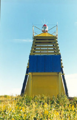 |
| This lighthouse on the Island of Maly Ainov is now operating on solar energy. |
| Government of the Norwegian province Finnmark. |
5. RTG decommissioning programmes
"This year we?ve signed a technical assignment with the US Department
of Energy for dismantling and decommissioning of several RTGs," the
head of the Minatom's safety and emergency situations department Agapov
told Bellona Web in September, 200348. According to Agapov,
"up to 100 RTGs per year will be decommissioned at Mayak�all the
transportation schemes have been prepared, the financial resources have
been promised."
Meanwhile, since 2000, VNIITFA has decommissioned only about 100 retired RTGs of various types.49
According to the current protocol, RTG cores are dismantled in a special laboratory at VNIITFA. The RHS-90 may be used for energy purposes or qualified as a radioactive waste and sent in special caskx for decommissioning at the Mayak.
Minatom's Agapov saw replacing RTGs with safe solar devices as problematic. "At current, replacement of RTGs with solar batteries has been underway for three years, and RTG decommissioning is carried out simultaneously�about 12 RTGs have been decommissioned in this manner. But then a problem emerges�solar panels need to be wiped regularly wiped down so they continue to collect heat energy, and personnel is needed for that."
In 2002, the Russia government launched a programme called "The National Plan of Action for Marine Environment Protection from Anthropogenic Pollution in the Arctic Region of Russia."
Accounting for RTGs was an item of the plan of action. It was, for example, decided to conduct a complete inventory of the RTGs in Yakutia during 2003 and 2003.50 Tamara Argunova, Yakutia's Ministry for Environmental Protection made the point that the RTGs were, in fact, redundant as most maritime navigations is accomplished with global positioning systems linked to satellites. She encouraged swift and diligent decommissioning of the RTGs in her area.
Rough estimates for the removal and complete decommissioning of one RTG in Yakutia come to 4m roubles51 or about $120,000�the price of installing a new RTG. According to VNIITFA, removal and decommissioning of an RTG in the far flung eastern region of Chukotka amounts to 1m roubles, or $30,000.52
RTGs owned by the Russian Northern Fleet have long surpassed their engineered life span and are considered radioactive hazards. Yet it is Norway's Finnmark region that foots the bill for their decommissioning and replacement of at least some of them with solar panels.
Indeed, there are several agreements between Finnmark and the Murmansk Regional government regulating RTG decommissioning. As per agreement ecommissioned RTG's are first sent for storage at Atomflot, the Murmansk region's service centre for nuclear ice-breakers that are owned by the Murmansk Shipping Company. They are then shipped to Mayak were the decommissioning is completed.
So far, five RTGs have been replace with Norwegian solar panels under one of the agreements between Finnmark and the Murmansk Region, signed in 1998, to swap four RTG's with solar panels.
The first was installed in 1998 at Bolshoi Ainov Island nature reserve at a cost of $35,400, or NOK 266,000.53 Under the 1998 agreement, another two RTGs were replaced with solar panels in 1999 and 2000. The last, in 2002, was installed at the Laush Lighthouse on the Rybachy Peninsula.
In further cooperation between Finnmark and Murmank, the two regions agreed to decommission 15 more RTGS�12 in normal working order and the three that were vandalised for scrap earlier this year.
In June, 2002, a $200,000, or NOK1.5m, agreement was signed between the regions to decommission yet another 10 RTGs.
In August, 2002, US Congressional representatives and Bellona gathered and discussed the prospects of solar powered lighthouses in Norway near the Russian border. Prior to this gathering Bellona had raised the concern about the nuclear powered lighthouses in Russia.54.
The governors of Finnmark and the Murmansk region, on April 8th 2003, signed two new contracts, one more RTG decommissioning, and the second for testing Russian-made solar panels. By now, 25 RTGs, with a combined activity of 800,000 curies, have been decommissioned in the Murmansk region.
The new 2003 agreement mandates the decommissioning of another 20, one of them a unique project in that it uses six RHS power sources and has an activity of 300,000 curies. This new agreement will cost $600,000, or NOK 4.5m.
That part of the 2003 agreement that will replace RTGs with solar panels will cost NOK 250,000. The Russian panels will be produced in Krasnodar at the Saturn plant, and are cheaper than western analogues.55 They cost about $30,000 each. The solar panel will be designed to accumulates energy during daylight hours, and distribute it to batteries and generators when the sun goes down. The Russian panels will be tested on a lighthouse in Murmansk and a lighthouse in Finnmark.
Endnotes:
1. Bellona Working Paper N5:92, Thomas Nilsen,. "Nuclear Powered Lighthouses," Oslo, 1992.
2. Information granted to the author in reply to an official inquiry to VNIITFA.
3. M.I.Rylov, M.N.Tikhonov. Problemy radiatsionnoi
bezopasnosti...//Atomnaya strategiya, St Petersburg, N1(6) June 2003,
p. 32. (In Russian).
4. Report on the activities of GAN in the
field of nuclear and radiation safety in 1998. Moscow, 1999, p. 72. (In
Russian) See also M.I.Rylov, M.N.Tikhonov. Problemy radiatsionnoi
bezopasnosti...//Atomnaya strategiya, St Petersburg, N1(6) June 2003.
P. 32. (In Russian).
5. www.vniitfa.ru/_Products/RadioNuclIst/RadioNuclIst.htm (In Russian).
6. Y.V. Klyuyev [head of the SHS of the Transportation Ministry.
Prodolzhayem razgovor...// Yakutia, Yakutsk, No. 59, April 1st 2000 (In
Russian).
7. Agapov's statements are a reply to the author's
inquiry about RTG decommissioning at a Minatom conference in St
Petersburg, September 1st 2003.
8. M.I.Rylov, M.N.Tikhonov,.
Problemy radiatsionnoi bezopasnosti...//Atomnaya strategiya, St
Petersburg, N1(6) June 2003, p. 32. (In Russian).
9. Information confirmed in reply to the author's official inquiry to VNIITFA.
10. Y.V. Klyuyev head of the SHS of the Transportation Ministry,
Prodolzhayem razgovor...// Yakutia, Yakutsk, No. 59, April 1st 2000 (In
Russian).
11. The Russian Ministy of Natural Resources. The State Report of 1999. www.ecocom.ru/Gosdoklad99/Part1-7.htm (In Russian).
12. The Russian Ministy of Natural Resources. The State Report of 1998. www.mnr.gov.ru/BUTT_R/5/2/Gosdoklad98/Part1-7.htm(In Russian).
13. Information partly taken from: A.M.Agapov, G.A. Novikov, Radiologichesky terrorism... www.informatom.ru/rus/safe/vena/Vena.asp
(In Russian), and M.I.Rylov, M.N.Tikhonov. Problemy radiatsionnoi
bezopasnosti...//Atomnaya strategiya, St. Petersburg, N1(6) June 200,.
p. 32. (In Russian).
14. Information granted to the author in reply to an official inquiry to VNIITFA.
15. A report on the activities of GAN?s branch of the Far Eastern
Interregional Territorial District in the field of nuclear and
radiation safety regulation at the sites of application of atomic
energy, first half of 2003 www.gan.ru/dvmto/otchet_1_2003.htm (In Russian).
16. The Russian Ministy of Natural Resources. The State Report of 1997. web.archive.org/web/20020223084209/http://www.ecocom.ru/arhiv/ecocom/Gosdoklad/Section29.htm(In Russian).
17. M.I.Rylov, M.N.Tikhonov. Problemy radiatsionnoi
bezopasnosti...//Atomnaya strategiya, St. Petersburg, N1(6) June 2003,
p. 32 (In Russian).
18. Information provided by the environmental NGO Kaira-Club, Chukotka region, www.kaira.seu.ru/kv/kv0902p2.htm (In Russian) See also: Report on the activities of GAN? 1997. Moscow, 1998, p. 72 (In Russian).
19. GAN Statement http://www.gan.ru/info82.htm (In Russian).
20. Information provided by the environmental NGO Kaira-Club, Chukotka region, www.kaira.seu.ru/kv/kv0902p2.htm
(In Russian), see also: M.I.Rylov, M.N.Tikhonov. Problemy radiatsionnoi
bezopasnosti...//Atomnaya strategiya, St. Petersburg, N1(6) June 2003,
p. 32 (In Russian).
21. Government of Sakha Republic (Yakutia),
the Ministry for the Protection of the Environment. The State Report
"On the state of the environment and activities in the field of nature
preservation in the Republic of Sakha (Yakutia) in 2001," Yakutsk,
2002, www.sterh.sakha.ru/gosdoklas2001/zakl.htm(In Russian).
22. Information on the violations of licencing terms and the violations
of laws, federal norms and regulations in the use of atomic energy,
information on the actions taken against the violators, third quarter
of 2002 web.archive.org/web/20021024163030/http://www.gan.ru/dvmto/nlic-3.2002.htm(In Russian).
23. N.R.Kuzelyov. A review of ?Problemy radiatsionnoi
bezopasnosti...?//Atomnaya strategiya, St. Petersburg, N1(6) June 2003,
p. 33 (In Russian).
24. Agapov's statements are quoted as a reply
to the author's inquiry about RTG decommissioning at a Minatom
conference in St Petersburg, September 1, 2003.
25. N.R.Kuzelyov.
A review of "Problemy radiatsionnoi bezopasnosti..."//Atomnaya
strategiya, St Petersburg, N1(6) June 2003, p. 33 (In Russian).
26. Ibid.
27. Ibid.
28. The Murmansk Regional Administration, Press release of 17.11.2003
No. 386 (In Russian). See also: Igor Kudrik, Rashid Alimov, Charles
Digges. Two strontium powered lighthouses vandalised on the Kola
Peninsula. http://www.bellona.no/en/international/russia/navy/northern_fleet/incidents/31767.html
29. Ibid.
30. Cape of Pihlisaar: 59�47'N 28�10'E.
31. Boris Karpov. Po tolstomu l'du. //Nevskoe Vremya, St. Petersburg, March 22, 2003, nevskoevremya.spb.ru/cgi-bin/pl/nv.pl?art=142016251 (In Russian).
32. GAN Statement www.gan.ru/4upr_spravka_2_2003.htm(In Russian).
33. The author's interview with head of Radon Alexander Ignatov, April 2003; press release of the NGO Zelyony Mir, www.greenworld.org.ru(In Russian).
34. Decree issued by the governor of the Leningrad region No. 309-pg of June 20th 2000, www.lenobl.ru/main2.php3?section=government4_32#Pril3 (In Russian).
35. GAN Statement www.gan.ru/dvmto/stat2.htm (In Russian).
36. Inventory of accidents and losses at sea involving radioactive material. IAEA-TECDOC-1242, IAEA, Vienna. 2001.
37. Marina Plechikova. Gotovitsya expeditsiya...// Svobodny Sakhalin, Yuzhno-Sakhalinsk, April 30th 2003 (In Russian).
38. Mikhail Gorbunov. Mstitel okhotskogo morya...// Rossiyskaya Gazeta, July 30th 2003. See also eco-pravda.km.ru/sreda/rg30il3.htm (In Russian).
39. Information granted to the author in reply to an official inquiry to VNIITFA.
40. V.V.Dovgusha, M.N.Tikhonov, Radiatsionnaya obstanovka na Severo-Zapade Rossii. St Petersburg, 2000 (In Russian).
41. Radiatsiya v tsentre Dushanbe. //"Azia Plus", Dushanbe, April 2002 ecoasia.ecolink.ru/data/2002.HTM/000147.HTM (In Russian).
42. Information granted to the author in reply to an official inquiry to VNIITFA.
43. Marina Plechikova. Sakhalin i Kurily mogut...//Svobodny Sakhalin,
Yuzhno-Sakhalinsk, No. 51(781), December 19th 2002 (In Russian).
44. See, for example, Anna Seleznyova. Radiatsionnaya lovushka...// Ekologiya i Pravo, No. 7, June 2003, P. 18 ( www.ecopravo.info); also see: Yevgeni Izyurov. Khronika luchevoi bolezni. //Vladivostok, N1330, 26th March 2003 ( www.vladnews.ru/magazin.php?id=11&idnews=9509¤t_magazin=1330). (In Russian).
45. web.archive.org/web/20030423022347/http://lugar.senate.gov/nunnlugar.htm
46. Report by Minister of Atomic Energy Alexander Rumyantsev at the
IAEA conference "Security of Radioactive Sources," Vienna, Austria.
March 11th 2003, www.iaea.org/worldatom/Press/Focus/RadSources/statement_rus.pdf
47. IAEA conference "Security of Radioactive Sources," Vienna, Austria. March 11th 2003. Findings of the Chair, www.iaea.org/worldatom/Press/Focus/RadSources/PDF/findings.pdf
48. Agapov's statements are quoted as made in reply to the author's
question about RTG decommissioning at a Minatom conference in St
Petersburg, September 1st 2003.
49. Information granted to the author in reply to an official inquiry to VNIITFA.
50. Government of Sakha Republic (Yakutia), the Ministry for the
Protection of the Environment. The State Report "On the state of the
environment and activities in the field of nature preservation in the
Republic of Sakha (Yakutia) in 2001," Yakutsk, 2002, www.sterh.sakha.ru/gosdoklas2001/zakl.htm(In Russian).
51. Yakutia. 38 iz 75 radioizotopnykh generatorov podlezhat
utilizatsii. Regnum News Agency, January 20th 2003 12:04 (In Russian).
52. N.R.Kuzelyov. A review of "Problemy radiatsionnoi
bezopasnosti..."//Atomnaya strategiya, St. Petersburg, N1(6) June 2003,
p. 33 (In Russian).
53. The Murmansk Regional Administration. Statement on the international cooperation of November 22d 2000, www.murman.ru/ecology/comitet/report99/part7_5.html(In Russian).
54. Thomas Nilsen. Nuclear Lighthouses to be Replaced. www.bellona.no/en/international/russia/nuke-weapons/nonproliferation/28067.html, Oslo, Febrary 2d 2003.
55. Pyotr Bolychev. Bolshe kron...// Murmansky Vestnik. Murmansk. April 12th 2003 (In Russian).