A collection of articles about schottkey diodes
Schottkey audio amplifier
The above hand-drawn schematic was provided by
Ludwell Sibley, with the comment that this had been hurriedly copied from a
Shockley Applications sheet years ago. This audio amplifier is clearly a most
unusual application for the Shockley diode, which originally was developed and
sold as a switching device. In fact, it seems that William Shockley was pleased
with this use of his invention, and made at least one professional presentation
in 1961 to an engineering group about the relevant circuit which article is
presented below.
Ludwell Sibley also relates another unusual application for the Shockley diode:
“I don’t know if I should admit this, but in college my dorm roommate was
enamored of listening to the theme song from a network show that aired at 11PM
nightly. This included nights before my early-morning ROTC drill. Fortunately
the radio signal was weak. A PNPN diode and 820-pF capacitor, wired in series
inside an AC plug, provided effective jamming action: 60 times a second the
diode would fire and send a pulse into the capacitor. The effect was
indistinguishable from loud fluorescent light noise.”
The relevant article is presented below
This is a reprint of a May 1961 column in Electronic Design magazine describing Shockley’s talk in Cleveland about the audio amp. Steve Scrupski wrote the original article and has provided some recent comments as well.
Attendees at Dr. William Shockley's lecture on four-layer diodes, given recently at the Eighth Annual Cleveland Electronics Conference, were treated to a demonstration of music played through an amplifier devoid of tubes or transistors—diodes were the only active elements. Response of the amplifier extended from dc to over 15 kc, with average audio power about 2 w. The improved version of the amplifier, shown in the circuit diagram, delivers about 10-w average audio power into a speaker or resistive load.
In basic principle, the device consists of two sections—a pulse-width modulator operating from the input signal, and a bistable multivibrator or flip-flop producing a square wave, which will vary in symmetry in accordance with the applied signal. A transducer, such as a loudspeaker, can be used to sense changes in symmetry and thus reproduce the original signal.
The modulator operates at 37.5 kc, more than double the highest audio frequency to be amplified. The modulator consists of a relaxation oscillator using a four-layer Shockley diode which fires at 40 v. When it fires, it discharges capacitor C1 through resistor R2, producing a 40-v negative pulse; a sawtooth waveform is produced at B at the top of C1-D1.
The modulator's second section is another four-layer semiconductor relaxation oscillator operating at 37.5 kc with this oscillator operating from a negative supply voltage to produce a negative-going sawtooth waveform at the top of C3-D2.
A voltage divider, R3 and R4, allows a small portion of the positive-going sawtooth, which appears at the top of C1-D1, to be applied to the bottom of D2; thus, D2 fires when the combined negative and positive sawtooth signals reach a difference potential equal to the firing voltage of D2 (in this case 50 v). When D2 fires , it discharges C3 through R7, producing a negative pulse of approximately 40 v.
The two relaxation oscillators operate in synchronism and the phase relation between these oscillators is affected by the sawtooth slope as well as the firing voltage of each diode. A small ac signal applied, as shown, changes the firing point of D1 and thus phase-modulates the pulses from D1 and D2. Symmetry is adjusted with R5 or R6.
The output stage is a bistable multivibrator consisting of two Shockley switching devices and is switched from side to side with the pulses supplied by the two relaxation oscillators. When no modulation is present, the speaker sees a square wave of 37.5 kc and a net audio signal of zero. As the symmetry is varied from side to side with an audio input signal, the transducer sees one diode conducting for a longer time than the other one; thus the transducer sees an audio component in the form of a zero-line shift. (Electronic Design, May 10, 1961, p. 216)
Shockley, an expert in the physics of p-n junction and multijunction devices, continued to come up with odd devices that never made it into the mainstream. I'm not sure how practical this circuit was, but it sure is interesting.
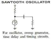
The basic Shockley diode oscillator circuit is shown above right. This is a sawtooth oscillator, which refers to the shape of the waveform generated by this circuit. Only three components are needed, in addition to diode, for this circuit. A Demonstrator Kit for the Shockley Diode (also known as the 4 layer diode, the pnpn diode or the transistor diode) was constructed at the Transistor Museum, using the basic sawtooth circuit. A photo of the completed kit is shown above. If proper values are used for the components, the circuit will oscillate in the audio range and produce a loud tone in an attached earphone.