|
How Arrays Work Virtually every digital design I worked on back in the 60's started with some kind of an array. My favorite arrays were built with small brass nails driven into a pine board in rows and columns. Probably every engineer has used an array to create a bank of switches for a keyboard or other computer or micro controller input device. I used arrays for ROM, RAM, Switches, Pilot Lamp Displays, adding numbers, subtracting numbers, and even multiplication. Here is a very basic example of a 7 place Decimal to Binary converter array: In the above circuit when PB6 pushbutton is held down current flows through diode D8 illuminating the L1 lamp & diode D9 illuminating the L2 lamp. So lamps L1 and L2 are on with L3 off. This is Binary 110 which is the Decimal 6. The same would be true of data bus at the bottom of the schematic DB-0 would be low through the filament of lamp 3 and DB-1. DB-2 would be high through PB6, & D8, D9. So the data on the bus = High-High-Low or 110 or Binary 110 = Dec 6. The pushbuttons could be contacts from a relay that was part of another circuit or a transistor or even an SCR if you wanted memory. So why the diodes?? If you substitute jumpers for D1 to D12 then there is a path for current to flow in between all of the vertical buses. Thus all the lamps L1-L3 would turn on when any button is pressed. You could substitute Push buttons that had multiple elements but that kind of switch is very expensive. By the early 60's when I started buying diodes for arrays they had gotten very cheap. There were a large number of mail-order houses that sold "unmarked" diodes that were intended for power rectifiers but had failed in manufacturing tests. They were sold in bags of 100 and as I recall they were about 7-10 dollars a bag. Often when I tested them there would be a few that failed the "battery test"... a lamp in series with a battery in series with the diode under test. So What If You Don't Have Any Diodes ? Another way to perform the same Decimal to Binary function as above is to use Neon pilot lamps and resistors. Before I went to low voltage logic circuits I built many Neon lamp based logic arrays.
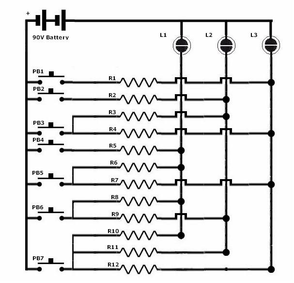
My best recollection is the resistors R-1 to R-12 were about 50K ohms. When PB1 is pushed current flows through R1 illuminating one half of L3. (neon lamps only light one element on DC) The other 2 lamps L1 & L2 are connected back to the vertical bus on L3 via the other resistors.. but the voltage never gets above the trigger value to illuminate them. Various logic elements could be isolated from one another by using the "Photo Sensitive" properties of the neon bulb. Mount 2 neon bulbs in a light tight enclosure in as close physical contact as you can. Put voltage on one of the lamps to just below the trigger voltage. Turn on the second lamp and the first lamp will turn on and remain on even after you turn off the trigger lamp. This made it easy to have several lookup arrays and not have any electrical interconnection between the two circuits. It also worked as a way to get a "latched output". This was very useful in using a common data bus and being able to isolate each circuit attached. |