 |
| Vladimir Polyakov (Вертикал Полякова), RA3AAE (on left) |
This 80m "Polyakov" direct-conversion "proof-of-concept" receiver uses a pair of vintage ferrite computer memory toroid cores in the subharmonic mixer. A 1.75MHz beat frequency oscillator (BF0) drives the ferrite cores along the full "B/H curve." The cores are driven alternately in and out of saturation twice per working cycle.
While the cores are saturated the inductive reactance falls to a low value and the signal from the antenna passes through the mixer with little attenuation. While the magnetic flux is passing from one saturation state to the opposite state the inductance rises (ideally) to a relatively high value. This high reactance momentarily blocks the antenna signal's path through the mixer. The idea is to create a commutating mixer from a time-varying, series reactance.
I'd hoped that it would be possible to hear 80m CW signals with only a pair of headphones connected to the mixer output. Unfortunately, the conversion loss is presently some 35 to 40dB higher than is typically seen with a diode mixer.
The mixer ON/OFF ratio ought to be roughly unity over the course of an incoming signal cycle, whereas my saturable reactor mixer spends spends far too long in the ON (saturated reactance) state. Another issue is the maximum reactance obtained in my present setup is too low in relation to the 50 Ohm path impedance.
In order to measure the "ON" feed-through signal loss an experiment was performed with the BFO signal replaced by a DC source. The current was raised until the inductors saturated. In this experiment I used a variable capacitance in series with the mixer signal windings in order to better cancel the residual inductance. I measured 1.46dB of signal attenuation. No improvement was seen with an RF choke placed in the BFO windings. This tells me the twin core signal cancellation technique (due to reversed polarity windings) is working well.
It wasn't quite so easy to measure the unsaturated feed-through signal attenuation under time-invariant conditions. When the DC bias test current is switched off the saturated ferrite cores simply revert to their remnant state. This is exactly what you'd expect of a semi-hard ferrite computer memory core. It's only possible to get an idea of the maximum reactance by reversing the DC bias polarity and slowly increasing the current; watching the 3.5MHz signal for the point of maximum attenuation. I measured a maximum total attenuation of 9.34dB. This "best-case" differential attenuation is only 7.88dB; which helps to explain why the conversion ratio is so poor.
This mixer working alone into the headphones (no semiconductors in the signal path) produces an audio beat-note with a few hundred millivolts of 3.5MHz signal injected at the antenna input terminal. Again, this is not exactly stellar sensitivity.
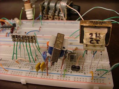
So much for the bad news. The good news is that I was able to copy a fair number of stronger 80m on-air CW signals using this mixer plus one stage of audio amplification. I used a 2N35 NPN germanium-alloy transistor that was made by Sylvania in 1956. Early evening code practice sessions from W1AW are easily copied anywhere in my (admittedly, tiny) shack with the headphones resting on the workbench.
I was careful to insure the input to the transistor amplifier is free of RF energy so there's no doubt the saturable reactors are providing the RF mixing action. Please notice the lack of a band limiting filter between the antenna and the mixer input. I expected this mixer would behave well in the presence of strong adjacent and out of band signals, and so it does.
My remote antenna coupler provides a return path to ground for audio frequencies. Lacking this, it would be necessary to connect a radio-frequency choke across the receiver antenna input terminals; something in the range of 1 to 2.5mH should work well.
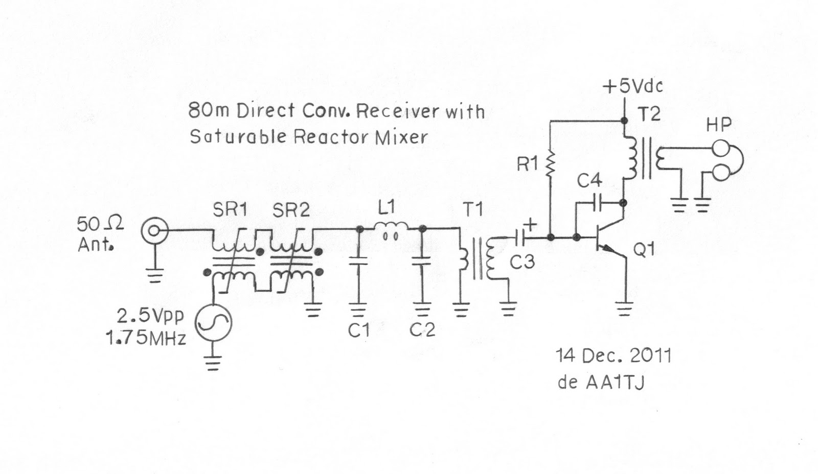
C1, C2: 1uF
C3: 100uF
C4: 330pF
R1: 330k Ohms
L1: ~3mH
T1: 50 Ohms to 1500 Ohm AF step-up
transformer
T2: 10k Ohms to 600 Ohms AF step-down
transformer
HP: 600 Ohm magnetic headphones
Q1: 2N35 (a mid-1950's vintage germanium
alloy transistor)
SR1, SR2: 50 turns on
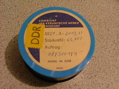
signal winding, 10 turns on BFO winding. The semi-hard, ferrite cores used in my saturable reactors, SR1 and SR2, each measure 1.27mm diameter by 0.395mm in thickness. They were made in the 1950's-70's for computer magnetic memory use by Kombinat VEB Keramische Werke of Hermsdorf, in the old DDR.
By the way, my saturable reactor mixer has much in common with a sensitive flux-gate magnetometer. Sure enough...a small magnet waved within 30cm of the mixer produces a curious "scratching" sound in the headphones. The same magnet set in place within 3cm of the mixer blocks all mixer action. I expect the external magnetic field simply prevents the BFO from effectively driving the core flux around the "B/H loop."
Here's a photo of the experimental receiver. The ferrite-based mixer appears on the left. The 1.75MHz BFO is in the background.
Here's the original container filled with tiny magnetic computer memory cores.