In-phase
splitter/combiner
by SV3ORA
This in-phase splitter/combiner, is suitable when you need to split a signal into two equal portions that are in-phase, or if you need to combine two same-phase signals into one. It may be useful in balanced mixer applications, where splitting and combining signals is required. It is suitable for receiving or for low level signals and it is constructed to be mini in size. The inputs and outputs are all 50 ohm.
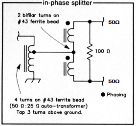
The splitter is composed of a resistor and two transformers. Each one of them, is wound on a FB-43-101 ferrite bead, thus two ferrite beads are required. I used 0.3mm diameter wire for all windings on both transformers.
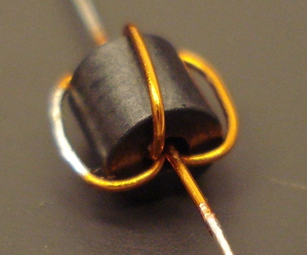
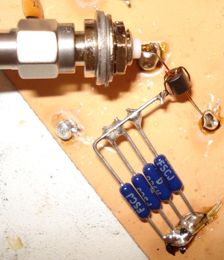
The transformer on the left of the schematic diagram, is an autotransformer, capable of converting a 50 ohm signal into 25 ohm. This 25 ohm, drives the transformer on the right. For the tap, I just stripped the enamel, as shown on the left in the above picture.
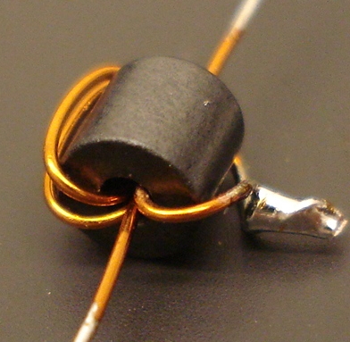
The transformer on the right of the schematic diagram, is an unbalanced 4:1 transformer. It transforms 25 ohms into 100 ohms at its output. The dots in the schematic diagram, indicate the starting (or ending) of the windings. This means that the dots represent the two individual wire ends, that exist on the same side of the transformer, before winding. Thus, to build it, you have to connect the end of the first wire (that is on the second side of the transformer), to the beginning of the second wire (that is on the first side of the transformer). As windings are bifilar, this requires flipping back one wire, from one side of the transformer into the other.
Testing the autotransformer is easy, using an impedance bridge and a signal generator. Connect the 50 ohm end of the transformer to the bridge test port. Then connect the other end to the GND. Finally connect the 25 ohms tap to an 25 ohm resistor (that can be made from four 100 ohms in parallel). Connect the other end of the resistor to the GND. Switch on the signal generator and observe the voltage out of the bridge. A good broadband match, indicates minimum voltage out of the bridge at all test frequencies. Changing the 25 ohms resistor to something else, should increase the voltage at the bridge, indicating mismatch.
Testing the unbalanced 4:1 transformer is easy as well. Connect one of the two 50 ohm ends with a 50 ohm resistor to the ground. Connect the other 50 ohm end, to the bridge test port. Finally connect the 25 ohms tap with an 25 ohm resistor to the ground. Note, the 100 ohm resistor, that connects the two 50 ohm ports, must be in place. Switch on the signal generator and observe the voltage out of the bridge. A good broadband match, indicates minimum voltage out of the bridge at all test frequencies. Interchange the 50 ohm ends and repeat the procedure again, to verify that the other 50 ohm end presents a good match as well. Changing the 25 ohms resistor to something else, should increase the voltage at the bridge, indicating mismatch.
If you do not have the equipment mentioned above, ignore these tests. I did them just to verify that the impedances are correct.
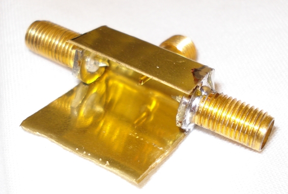
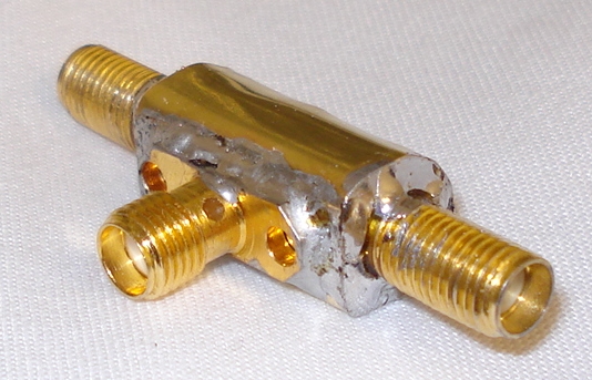
The enclosure was made out of a small brass sheet, folded in such a way to hold the connectors. The connectors then soldered directly onto the enclosure. This technique is quick and dirty and it looks ugly, one could argue. However it is probably the best for RF.
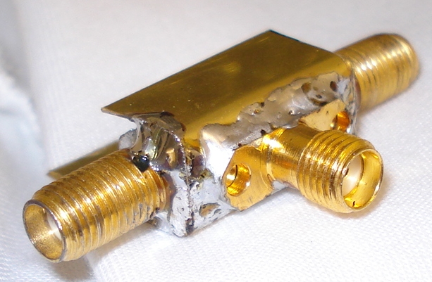
The connectors used were SMA. To minimize even more the size, I could use SMB as well. However these are more expensive and require harder to find and solder cables. Why not using the standard SMA then?
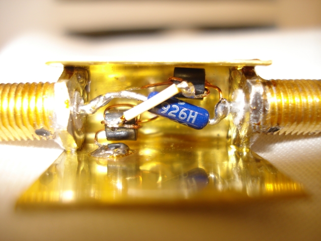
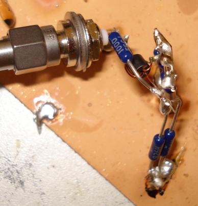
Picture above, shows the connections inside the enclosure. Components are tightly packed. About soldering, forget lead-free solder. Lead-based solder is flexible, reliable, joins best on metals such as brass and makes bright shiny solders. Just wash-up your hands when finishing construction and every time you finish your job, after you have touched the enclosure. After finishing the whole construction, clean the enclosure and connectors with oil-free acetone, to remove any resign remains.
The splitter operation can be tested with a dual channel oscilloscope and a signal generator. Connect the signal generator to the input and each of the two outputs to a channel on the oscilloscope. Calibrate the levels of both channels on your oscilloscope to be equal and switch on the signal generator. At all frequencies, you should notice two equal phase and amplitude signals. Then your splitter works perfectly ok.