RF
power switch for your rigs
Designed
by sv3ora
When I started collecting vintage rigs, I
ended up in a line of rigs on my bench, that were sitting there,
disconnected from any mains cables or the antenna. I wanted these rigs
to be ready to fire at any time I wanted to, without having to
connect/disconnect cables all the time. I also wanted to be able to
compare different rigs performances at the flip of a switch, which is
the only way this can be done on the HF quick fading conditions. For
power cables, the solution was to leave them connected in the mains
plugs all the time. My
rigs that have an internal PSU, have mechanical switches, so they are
isolated from the mains when they are switched off. The rigs that are
powered by an external PSU, depend on the external PSU main switch for
isolation (in case they haven't mechanichal switches on them), which in
my case is mechanical and switches off the mains power, when the PSU is
switched off.
However, for the RF cables, this was a different story. Having only one
antenna and multiple rigs, means that you have to connect each rig to
the antenna every time you want to operate each rig. This is not only
borring and time consuming (you have to reach the back of the
transceivers to connect/disconnect the conenctors), but eventually
causes the connectors of the coaxial cable and the rigs to wear out. I
decided to make things better and make an RF rig selector for my rigs.
After a bit of brainstorming, the circuit
I ended up is shown below. The circuit is able to switch a common
antenna to four different rigs. Why four? Because this was the capacity
of my switch and the number of connectors I had available. If you have
a greater capacity switch and more connectors, expand the circuit to
your needs.
Notice the connections in the circuit. One section of the switch is
used for the positive wire (central conductor of the coaxial) and
another for the negative (braid of the coaxial). Why is that? This is
because I canted to add a special feature to the switch. That is, the
ability to disconnect the antenna from any rig when the rigs are not
used. Previously, I used to disconnect the antenna coaxial from the
transceiver when I was away, so as to protect the transceiver from
antenna static discharges and possibly destroy it's front end circuits.
Now, with a single flip of the switch, I am able to do so. Because I
wanted the switch to operate on different types of antennas (balanced
or not) I decided to short circuit both poles of the antenna at this
position, to equalize their charges.
But equalizing their charges was not enough. I had to find a way to let
these charges go to the ground, so that the antenna is discharged.
Directly grounding the short circuit, did not seem a good thing to do,
because the whole wire antenna on the roof would be grounded. Whether
this is a good idea to avoid lightings or not, I do not know. So I
decided to keep the short circuited antenna floading and instantly
discharge it only when adequate static charge is built upon it. For
this purpose, I used a neon tube, permanently connected to the switch
NC (not-connected) position. When the switch is in the non-connected
position, the tube
lights up and discharges the antenna (both poles) if an appropriate
amount of static
charges has been built upon it. When the switch is in any of the
selected rigs connections, the tube is disconnected, preventing it from
lighting up when you transmit into the antenna. Note that this
configuration, requires that the output
(antenna) coaxial connector must be isolated from the metal chassis of
the RF switch.
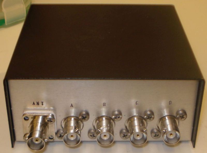
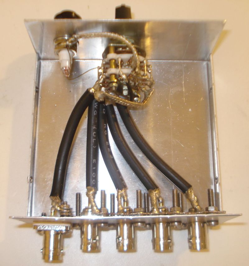
The next image, shows the back of the
metal chassis used for the RF switch. Note the isolated ANT connector.
Isolation has been done with a PVC sheet and isolated screw rings. Also
note the usage of BNC connectors. I used BNC connectors for various
reasons. They are excellent connectors with quick lock/unlock features.
You do not need to screw them (and wear them out) and once fit in place
they are not unscrewed. Once fitted in place, they allow for rotating
the connection without unscrewing the cable or bending it. They can
handle 100W easily. Despite all these features, they are much smaller
in size and lighter. Their reduced size fits easily to reduced diameter
cables like the RG-58 and similar. In an RF switch where there are lots
of cables connected, this does make a difference. They are also very
common and very cheap. There are even types that do not require
soldering at all to fit a coaxial to them. I use BNC connectors even at
my antenna side, as they have been proven to be quite waterproof. The
types of BNC connectors I choose are not silver plated. Despite silver
plated connectors are better, in the long term they are corroded by
humidity and become much worst than the nickel plated connectors. The
sonnectors I used are nickel plated with gold plated central conductors.
I have found these types to be much more durable over the years,
despite being cheaper.
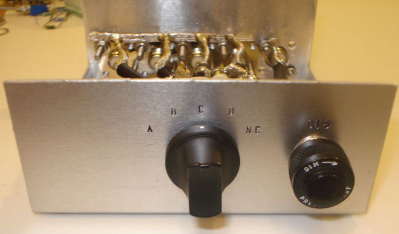
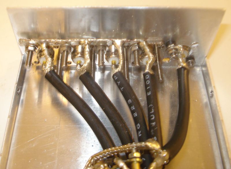
Below is a first look at the internals of
the RF switch. The BNC sonnectors used, are the square flange types. I
used this type of connectors because when they are fitter onto the
chassis, they cannot be unscrewed, unlike the single-hole types. The
coaxial cable used for the internal switch connections, is the RG-223.
This cable is silver-plated (both the central conductor and the braid),
it has double braid for increased shielding, it is of the same diameter
as the RG-58 and it has a bit lower loss. The cable loss is negligible
though for such small pieces of cable. The same type of cable has been
used for the internal switch connections as well as for the connections
of the switch to the rigs. Appropriate lengths of RG-223 cables were
cut and fitted with BNC connectors at one side and the appropriate rig
connectors at their other side.
All the coaxial input cables are grounded at the connectors side. I
used a piece of coaxial braid and fitted it to the connectors screws.
Then I soldered the braids of the coaxials onto this piece. Notice the
black ring screw isolators at the antenna connector, to isolate it from the
chassis. Speaking about the chassis, do not use a plastic chassis for
the RF switch, use only a metal one!
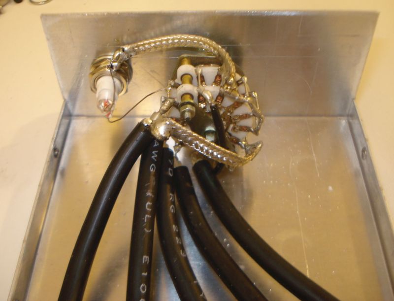
Below is an overal view of the internal
construction of the RF switch. The coaxial cables are soldered onto the
switch contacts. Where a ground connection is required, a piece of
braid accomplishes this. Do not use thin wires, the device has to allow
for at least 100W of HF RF power to pass wthrough it. The neon tube
directly connects to the appropriate switch contact and to the chassis.
The most important part of an RF switch
is of course the switch itself. For 100W of HF RF power, I would
suggest you to use a porcelain switch. I had a 5-positions 4-sections
small porcelain switch, which I used. I connected two sections at each
side in parallel (adjacent pins connected together). That is, two
sections in parallel for the positive wire and two sections in parallel
for the braid. I did that for various reasons. First, by using two
contacts for each connection instead of one, you increase the power
handling capability of the switch. Then, you ensure a sure-contact
throughout the years. Any corrosion or wearing on the switch contacts
would cause contact problems eventually. By using two contacts for each
connection instead of one, you double the probability for a good
contact. After all, I had a switch with more sections, so why not make a
good use of them?
The results from the RF switch operation
are quite satisfying. The overal construction is kept small and low
profile. The switch makes a good contact despite being small. The
automatic discharger seems to work well. On receive, there is some RF
leakage, as I expected, in the near by cables, which is noticed in the
higher HF bands or in very strong signals. The very sensitive receivers
we use, are able to detect that. This RF leakage occurs even when the
switch is in the NC position, where the antenna is disconnected and
floating. So, to be honest I have
not figured out if the leakage is from the switch or from the external
cables in the shack. On TX, there is of course severe leakage from the
transmitting coaxial to the rest of the ports. This IS expected. There
is leakage even without using any switch at all, in the nearby
receivers, when a transmitter operates at such high powers. There is
nothing you can do about it really, unless your receiver has a mute
capability.
The most important thing though, is that the goal of this project was
achieved. I am able to switch the antenna to whatever rig I want at the
flip of a switch. And before I go away, at the flip of a switch I can
isolate and automatically discharge the antenna when needed. This is so
much more convenient than having to connect and disconnect cables all
the time!
Back to main
site