A small-sized low phase noise OCXO for lab measurements, microwave IF processing and MXO applications
by SV3ORA
A reference oscillator is a very important piece of equipment for any RF laboratory. It enables relative measurements and comparisons of the characteristics of other test oscillators, mixers and the rest of the RF building blocks that you may build. In microwave bands, it can be used on MXO applications, IF processing or in combination with low noise mixers, to create high performance microwave signal generation. The importance of having such a piece of equipment at the workbench, led me to the design of a universal miniature reference oscillator.
There are quite a few ways to implement such an oscillator,
but most of them, make use of a quartz resonator driven at low current. My
experiments are based on discussions I had with other people, amateurs and
professionals
(especially experts from Wenzel Associates Inc.) THIS TO BE REMOVED, I HAVE
GIVEN THANKS AT THE BOTTOM OF THE ARTICLE,
and the articles I have read throughout the years. From these articles and
discussions, I distinguished some bright ideas, which I am trying to
implement in this oscillator.
Key features of the mini reference oscillator:
Project files
Schematic (PDF)
Schematic (ExpressPCB)
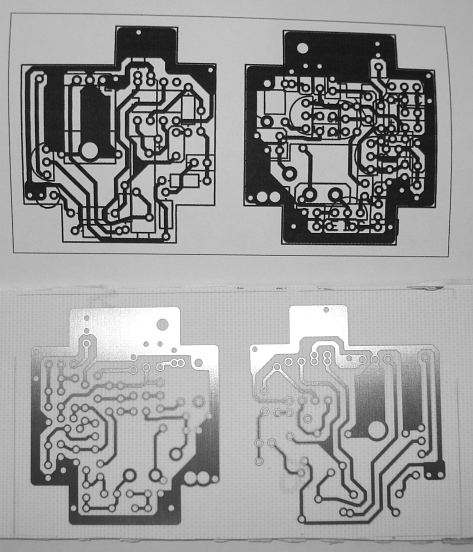
Bottom copper layer (PDF)
Bottom copper layer (ExpressPCB)
G101 enclosure (PDF)
G101 enclosure (DWG)
G101 enclosure photo (PDF)
Double clicking on each component on the expressPCB copper layer file, will
notify you which value is it. For readability reasons, I did not include the
components values on the silkscreen layer.
The circuit
The schematic is shown in the next picture. Starting from the left to the right, first there is a simple voltage follower. Despite being simple, this type of follower is of quite low noise and it effectively removes hum from a noisy PSU. I did not use a voltage regulator like a 7811. There are three main reasons for this. Firstly, I wanted the oscillator to operate from different PSU sources and voltages (achieving potentially different output characteristics), as it is indented to be used on the lab bench. Secondly, the use of a typical three-terminal regulator like the 7811, would require at least 14v as an input voltage. Third and most importantly, are noise reasons. Ordinary three-terminal regulators have several hundred nanovolts per root-hertz of white noise and some reference devices exceed one microvolt per root-hertz. The main 12v power source for the circuit can be anything from a 7812 regulator to a lab power supply or ideally a 12v battery. The total current consumption of the oscillator when the crystal oven is on, is about 130mA at 12V going down to about 30mA when the oven is off. It periodicaly goes up and down between these two values as the oven is switched on and off.
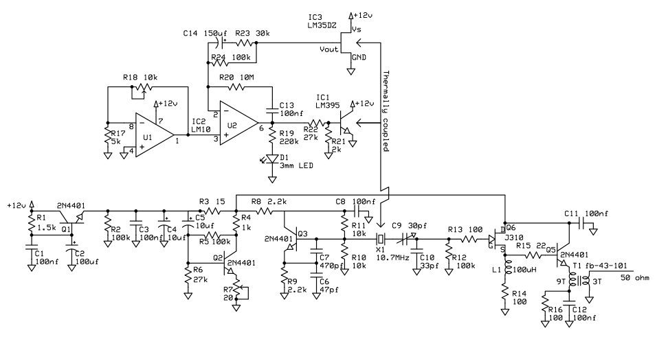
Note that there is
no series decoupling (resistor or RFC) between the drain of Q6 and the
positive supply rail. Everything is done on the lower side of the
amplifier transistors (emitter/source), as a try for keeping the
amplifier noise down. One
could argue that this could lead to a problem because the bypass
capacitor C11 is then shared with Q2 and Q3, as well as Q6 - in effect
coupling them all together. Actually
for Q2 and Q3 this is not a problem,
as there are series resistors at the collectors. For Q5 and Q6, this is
not a problem as well, as they have different isolated source/emitter
circuits. There is not too much difference in taking the signal from the
collector/drain or the emitter/source, apart from the phase difference.
The amplifier transistors share a common decoupling capacitor but they
are too close together on the PCB, so there is no need for an extra
decoupling capacitor.
|
|
The construction of the transformer T1 is simple. Wind 9 turns of 0.1mm-0.2mm enameled copper wire, on a FB-43-101 core. Then wind another 3 turns. Separate the primary and secondary ends as much as possible. As you wind the turns, take care not to remove the enameled paint from the wire by the sharp edges of the ferrite core. |
The crystal oven
High performance crystal oscillators employ temperature control circuitry to
hold the crystal at a precise, constant temperature. A carefully designed
OCXO yields temperature stabilities as good as 0.0001 PPM over a temperature
range that would cause the crystal to change by 10 PPM. Since size is a
constraint in this oscillator, an
LM10 operational amplifier and voltage
reference was used as the oven controller. Semiconductor devices are also
used for both heating and temperature sensing. This leads to a simple
circuit, but with better characteristics than the much simpler thermistor/resistor
circuits. The main reason LM395 was used as a heating element, was it's
small size compared to other heating elements and the easiness of mounting
onto the crystal, resulting in an overall small sized structure. The
semiconductor device was though to be more reliable as well. With this oven used, the stability of the oscillator when pre-heated, is better than 1Hz.
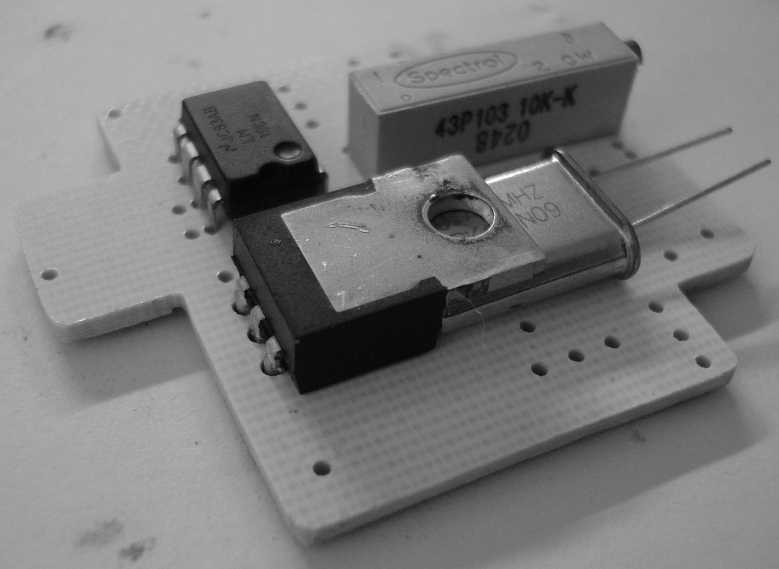
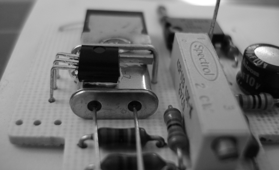
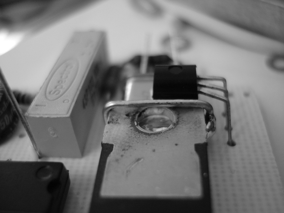
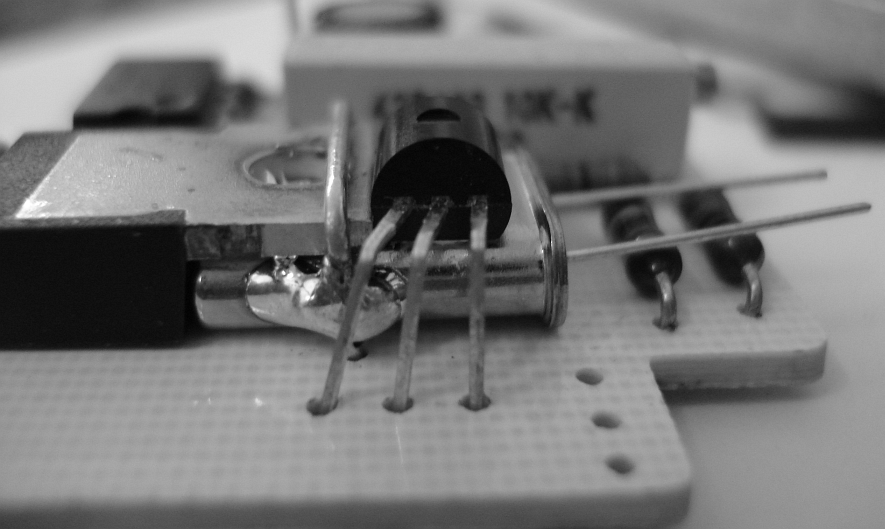
The tricky mechanical part of the oven, is the mounting of the crystal to the heater. These pictures show the mounting of the crystal below the LM395, which is placed upside down on the PCB, in order to leave space for the crystal to slip below it.
|
|
|
|
|
|
The LM35DZ is directly held onto the remaining body of the crystal, using a small amount of thermal-conductive glue.
|
|
|
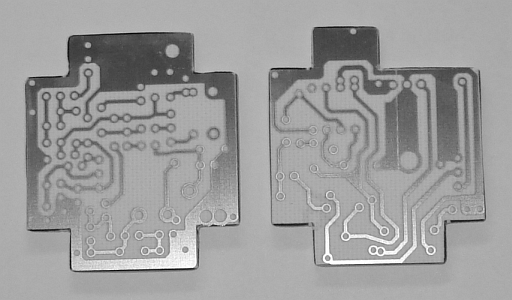
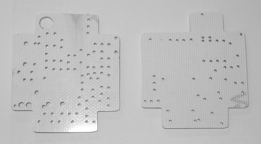
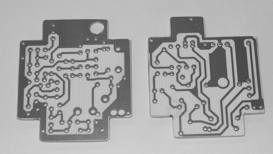
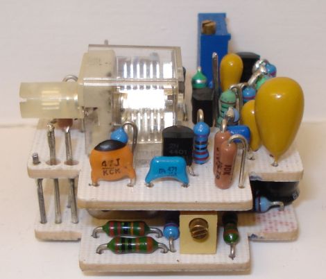
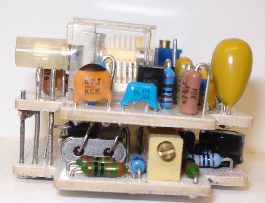
Overall construction
The oscillator is composed of two PCBs, connected together in a modular way, so that they can split apart if needed. The bottom PCB is the crystal oven, whereas the top PCB is the oscillator circuit. If one decides that he does not need a OCXO, then the oven PCB can be left out, without affecting the rest of the oscillator circuit.
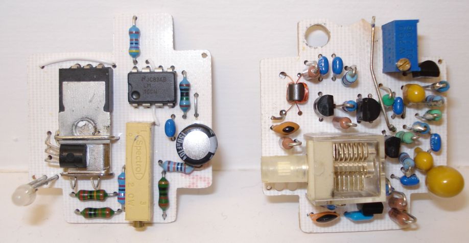
The oven PCB has just three connections to the oscillator PCB, one for the positive voltage and two for the ground. The two PCBs are sandwiched together, with these three connections interconnecting the top and the bottom PCBs.
|
|
|
|
|
|
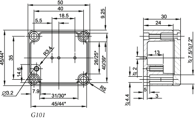
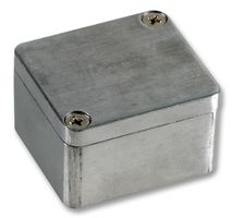
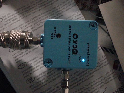
The whole circuit is enclosed inside a Gainta G101 die cast box, the smallest of the G-series. It's dimensions and look, are shown below.
|
|
|
Space inside the enclosure is very limited. The bottom PCB pins are just touching the metal box below. To prevent short circuits, a thick insulating membrane was added between the bottom pcb and the enclosure.
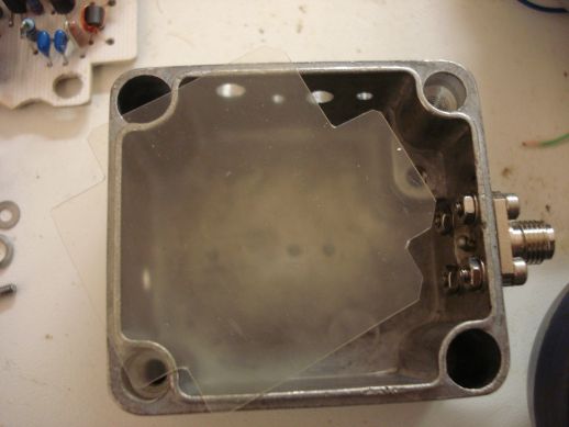
When the two PCBs are sandwiched together and just before enclosing them in the box, a small amount of polyurethane foam is inserted between them, such as the crystal and the heating circuits are completely surrounded by the foam, creating a thermal insulation.
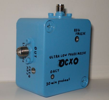
I used SMA connectors for both the RF output and the PSU line because of their small size, but any RF connector can be used at these low frequencies. I have chosen to use a coaxial connector for the PSU line, to shield it from external noise. Bare wires used for the PSU line, can pick up external noise and transfer it inside the oscillator circuits. A shielded coaxial cable to connect the OCXO to the PSU is the best.
Evaluating the noise performance
For testing the oscillator noise performance, an E5052A signal source analyzer has been used. The results are quite satisfying, although there is a window for further improvements to the circuit. The results of the measurements are shown in the next pictures.
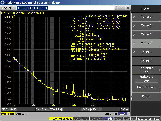
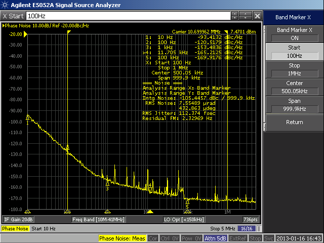
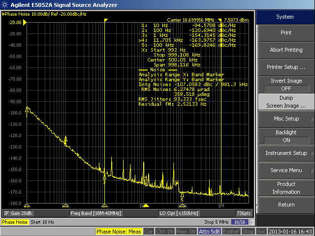

The noise floor is about -170dBc/Hz, which is really interesting. The curve gets "white" somewhere at 10 kHz frequency offset. A cause of the spikes on the plot, could be co-resonances of the crystal or problems related to the bias levels transistors or the output transformer. Adjusting the noise suppression circuit brought no actual improvement. Nevertheless, these spikes were not visible with a different testing equipment and I have been told it's virtually impossible for that circuit to have so much flicker. The instrument showed also that the time jitter decreases noticeably, if one increases the lower integration limit from 10 Hz to 100 Hz, 1 kHz etc.
Tuning the crystal oven
Most
oven crystals you will encounter are AT-cuts and they have a
bowl-shaped temperature curve above room temperature. The idea is to
find the bottom of that bowl where the slope is nearly zero so that
slight changes in temperature don't change the frequency much.
Remember
that AT-cuts dive in frequency when heated, going below the actual
curve. Give the crystal time to recover from that thermal shock before
determining the frequency. Using Spectrum Lab will give you a plot of
the frequency so you can see the exponential recovery from the thermal
shock. The opposite is true for suddenly cooling the crystals.
A
simple way to see what is the best point for the oven temperature by
using a particular crystal, could be to tune an SSB digital
receiver to the crystal frequency, then connect its audio output to a
spectrum analyzer program like spectrum lab in it's waterfall display.
As you tune the oven temperature you will be able to see at the
waterfall, the audio tone frequency changing. By trial and error
you should be able to find the best point where the curve of the
crystal temperature gives the best stability.
Finding the best point for the oven temperature is ideal, but if stability of about 1Hz is enough, you do not really have to get too tired finding this point. In my case I achieved a stability better than 1Hz with no consideration of that point at all and by just adjusting the oven at a temperature of a few degrees greater than the environment temperature. I did not use a crystal designed specifically for an oven, I used an ordinary 10.7MHz crystal, so I thought it would be a good idea not to overheat this crystal too much, for various reasons explained later in this article.
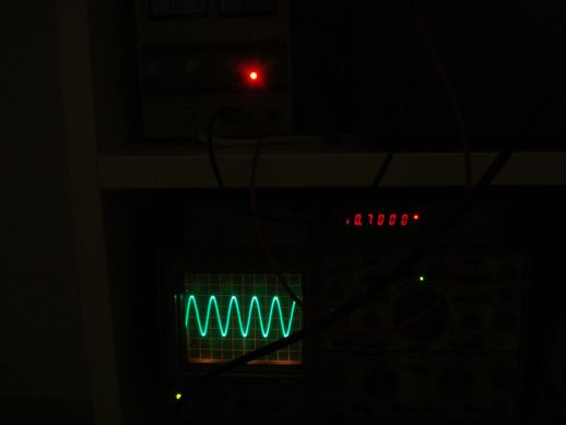
There are many ways to tune a OCXO but I tuned my OCXO by connecting a 12v power to the appropriate connector and placing the oscillator near a digital shortwave radio using a small SMA rubber antenna.
Switch on the radio and tune it to 10.7MHz with the bfo switched on. Pick up the AF tone signal from the receiver and connect it to a computer running Spectrum Lab or any other waterfall program. You will then notice the AF tone signal in the waterfall.
Tune the oven temperature in the point where the LED just switches on. Then the oven is set a few degrees above the environment temperature. You may try different temperatures, but remember, the result must be a stable output frequency. Also note, after each setting you have to give the oven much time to stabilize. In my case this time was as long as 30 minutes.
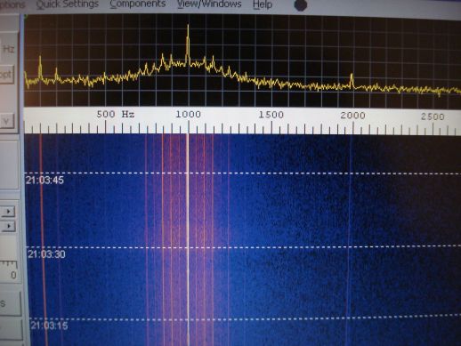
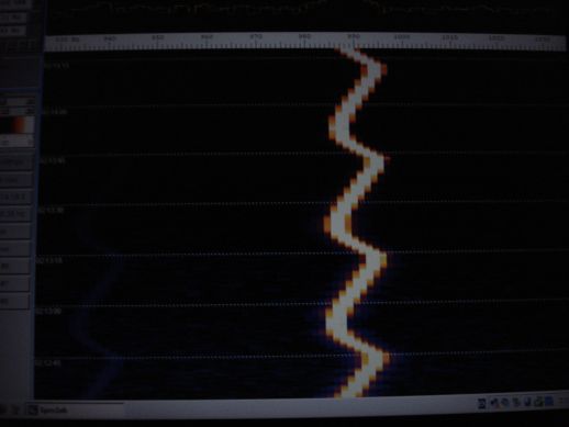
Zoom in to that signal and you will notice frequency oscillations like shown above. These frequency oscillations occur because the control loop oscillates, when the temperature sensor is placed far away from the heater. Having the sensor on the opposite side of the crystal for example, can introduce a time delay which makes the feedback loop unstable. In this oscillator, the temperature sensor has been placed very close to the heater, but these oscillations are not avoided and they would occur for some time until the control loop stabilizes.
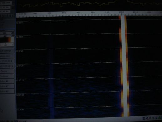
After about 30 minutes these oscillations almost disappear, as the oven stabilizes.
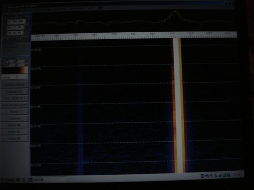
After about 35 minutes, there are no oscillations. The OCXO is stable to the Hz then.
As you tune the temperature of the oven (and thus the temperature of the crystal), the output frequency of the OCXO changes. When finishing tuning the oven, connect the output of the oscillator to an accurate frequency counter. Then tune the frequency tuning variable capacitor to bring the oscillator to the correct frequency. Each time your OCXO is fully preheated, this frequency must be shown on the frequency counter.
A note of warning about ovenizing
ordinary crystals
An
oven will not degrade the noise of a crystal designed for an oven. In
fact, most crystals will exhibit much better close-in noise when
ovenized because tiny temperature changes can push the frequency of a
crystal around quite a bit. We are talking about "noise" that is very
close to the carrier, maybe below a couple of Hz. Also, an oven allows
the crystal to be a very specialized, highly polished type that might
very well have bad activity dips below the oven temperature. In other
words, crystals designed to operate over a range of temperature have
design restrictions that will impact the Q and noise in a negative way
compared to a crystal designed to operate at only one temperature.
You can use an "ordinary" crystal in an oven if you don't heat it very hot. The main problem with heating an AT-cut well past its intended temperature range, is that the frequency/temperature slope can get very steep, making the oscillator sensitive to small changes in temperature. But an oven at 40 or 50C should be fine for most room temperature cuts. The symptom of going too hot will be a steep rise in frequency for a small increase in oven temperature.
But is the phase noise
compromised when heating on 40-50C? A crystal running off turning point is
much more susceptible to thermal variations. So at very low frequency
offsets the phase noise can be degraded. If the oscillator wanders around a
few millihertz due to thermal noise, that's close-in phase noise. This would
only be noticeable at offsets below a Hz or two.
Since there are different crystals with different characteristics, there is
not an obvious general rule of thumb to follow. A good starting point could
be that, if
noise performance is more important than frequency stability and if you
find that the crystal you have used, has bad measured characteristics when
heated, you may want to replace the crystal with another one or a more
suitable type or at the worst case completely switch off the oven, by
setting the threshold temperature to the lowest value, so as the oven
is never turned on and the crystal operates at room temperature. If room
temperature does not change at extreme values (which is often the case) and
if a "room temperature" crystal is used, then there may be no need for
switching on the oven at all. Even in that later case, the crystal still has
to be surrounded by thermal insulation, as a protection against sudden (but
low duration) thermal shocks.
Can it be made better?
The
oscillator oven is quite good as it is, but it could be made even
better. A good starting point would be to heat up all the components of
the oscillator and not just the quartz resonator. The thermal
insulation should then cover the whole enclosure and not just the oven.
Even better, a Dewar Flask could be used instead of foam or armaflex,
to give a much greater thermal isolation. The heat-up time might then
be much greater, but all components would be eventually temperature stabilized. The
oscillator enclosure should then be made much larger and more
air-proof, allowing air inside to be gradually heated up and transfer
the heating to the various components.
Despite this approach was
not followed, mainly for size constraints, the rest of the oscillator frequency
critical components used, are of very good quality and low ppm values, so
that they are not much affected by temperature variations. All the resistors in
the oscillator portion are about +/-30ppm and the capacitors in this portion
are NP0 (+/-30ppm). Temperature compensation of the oscillator components
(apart from the crystal) was not thought to be necessary, although you may
want to try some negative coefficient capacitor combinations and evaluate
the results. Also, extreme thermal or radiation bursts were not applied to
this oscillator, so if you intend to use it in tough environments, you may
wish to do your own experiments, if you have the necessary testing
equipment.
Other possible improvements could be made on the power supply circuit or including a discrete voltage regulator if one needs to keep the oscillator voltage stable throughout different input voltages. Accurate low phase noise measurements are quite difficult to perform so I do not know if altering components or their values could improve the phase noise performance even more. Nevertheless, I think the overall performance of the oscillator is very satisfying for such a low cost circuit, possibly far better than many commercial oscillators.
Thanksgiving
The design and implementation of this oscillator, took about two years of continuous discussions with engineers from Wenzel Associates, trying to figure out of a low noise approach. Special thanks to Charles Wenzel, who was always willing to help me on this. Also, I have to thank DUBUS magazine and especially DL8HCZ for the communication and DK5LV for the evaluation of the oscillator.
References
Time and
frequency related files - Wenzel Associates
DJ2LR very low
noise xtal osc