An all-bands random wire antenna
by sv3ora
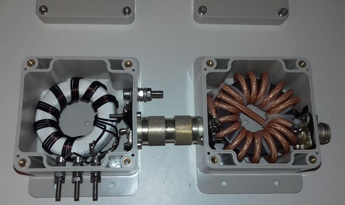
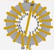
The
multi-impedance transformer has 9 quadrifilar turns wound onto an
FT240-43 toroid and connected as shown in the next schematic. The
9:1 tap is only used for the random wire antenna. Other taps are there
is other types of antennas are to be tried in future time.
The choke has 18 turns of RG-142 coaxial cable, cross-wound (Joe Reisert method) onto an FT240-43 toroid.
The monopole antenna wire length should be one from the table below.
The band column show the lowest band that the antenna can operate
properly, with the corresponding length. Obviously, choose the longest
length based on your available space.
band mt wire meters
-------- -----------
20 8.84
40 10.82
40 12.50
40
17.68
80
21.64
80 25.60
80 32.61
80 36.27
160 45.11
160 61.87
160 105.77
160 124.05
160 128.93
You must also connect a counterpoise at the ground connection of the
transformer, for the antenna to work properly. A good counterpoise for
a random wire antenna should have a length of 1/4 lambda at the lowest
operating frequency (which for the 160m band means 40m). Such a
counterpoise may be just laid down on ground in a straight line and/or
looped around, trying to keep the loop as large as possible.
Alternatively it's possible to connect a run of wire from the
counterpoise connection to the ground and, from there, run whatever
number of radials of various lengths and in various directions.
Special thanks to my friend Andrea from Italy, for pointing me in the right directions in building this antenna!
UPDATE 17 May 2023
------------------
After a few years of operation of this antenna, I noticed changing in
the tuner behaviour and eventually burnt out the tuner inductor
selector switch. I thought it was a faulty cable connection, until I
opened the transformers enclosures only to find out that these were
full of humidity and some water inside (apart from some bugs).
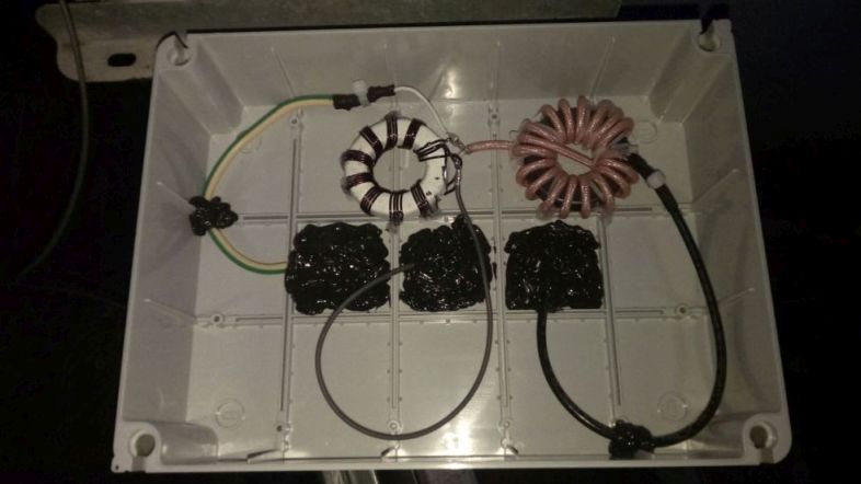
Therefore I built a new antenna from bottom up.
I replaced the 2 connected coaxial cables up to the antenna, with a
single piece of Airborne 5 cable, of about 35 meters. I pass this cable
through a drain pipe and this is now mostly invisible and most
importantly, not hanging around. I removed the transformer and the
choke from their enclosures and I placed them in a single big
enclosure. Whatever I did, I took care of the water insulation this
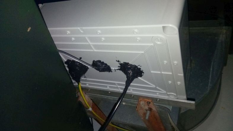
time. No connectors were used, the cables pass through the enclosure
with three small holes and these filled with loads of water insulating
silicone, both inside and outside the enclosure. The holes have been
done at the bottom of the enclosure and nead the center. Around of
them, there are fins that ensure the water droplets wont easily reach
the cable holes. I placed the enclo sure in such a way that the natural
water flow does not reach the rubber insulation of the cap at all. Here
are some pictures of the setup.
The new antenna has been converted to inverted L type and it has a
total wire length of around 36.2m, with the 25.6m being in the
horizontal wire. Starting from near the ground, provided easy access to
the transformers enclosure and it also allowed for sticking a ground
stake for better RF ground than before. This time, no connectors have
been used anywhere. Everything is soldered inside the enclosure, to
ensure ever-lasting contacts. All the screws and metal parts used to
mount the enclosure, are made of anodized aluminum and stainless steel.
Also, the antenna wire itself, is a single piece of 1.5mm stranded
copper wire, starting from inside the enclosure and ending to the far
end of the antenna. There are no connections exposed to the rain
anywhere on the cable length. The cable is twisted (along with its
insulation) near the porcelain egg insulators at the antenna ends and
passing through the middle (corner) egg insulator.
Back to main site