Potentiometer
noise tester
by sv3ora
We use potentiometers all the time,
either as potential dividers in audio volume or varactor controls, or
as variable resistance elements in many other circuits. Unfortuately
potentiometers, due to their mechanical nature, can go very easily bad
and cause a lot of problems. Moisture, dust and usage, all affect the
quality of the potentiometer. Problems can be caused in the carbon to
metal wiper contact point, or to the metal to metal contact of the
wiper and the central pin of the potentiometer. Unless a potentiometer
has been physically damaged or had enough current through it to burn
the track, most of the noise doesn't come from the wiper to carbon
track contact, it comes from the deteriorated metal to metal contact to
the center pin.
I have not come across a suitable tester for noise in potentiometers,
so I had to design one. An attempt is made here to quantify the noise,
or at least grade the quality of the potentiometer control by slowly
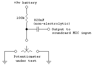
rotating it and noting the noise in the result. The circuit of the
tested is shown below.

It is essential there is some DC there otherwise the sudden changes in
current that cause the noise cannot exist. What you have to remember is
that a potentiometer, no matter how bad it is, does not create noise by
itself, it is currents from the signals, coupling capacitor leakage and
any intentional DC that cause it. Essentially, the voltage that causes
sudden changes in resistance is made evident within the audio range and
that's what we hear as crackle.
We should deliberately introduce a small current (microamps) through
the wiper to ground so it results in a voltage change for subsequent
amplification. The current will diminish as the resistance increases
and hence less noise noticed. This would be particularly noticeable if
just one end of the potentiometer was grounded. Then the ends of the
potentiometer should be swapped and the test should be repeated. In my
circuit, both ends of the track are simultaneously grounded so that the test is only performed once. It isn't the ideal solution but it does test it over more of the track length at once.
We have to ensure leakage into the amplifier is very low, preferably by
coupling through a non-electrolytic capacitor, as natural leakage
through an electrolytic might upset the measurement. When performing
the test, it is important to remember to turn the potentiometer slowly,
about 5 to 10 seconds for a complete turn. Turning a "healthy"
potentiometer quickly will introduce noise, despite this potentiometer
is supposed to be good.
Back to main
site

