
Crystal oscillator oscillates in more than one frequencies simultaneously!
During
my experiments with my all-HF-bands crystal oscillator, I came up with
a weird idea. Since the crystal was connected at the output of the
circuit, I thought that maybe if I use crystals of different frequencies,
connected in parallel at the output of the oscillator, I could have an
oscillator that
could oscillate at more than one frequencies simultaneously. This was
something I have never tried before and I have not found any
information about it in electronics magazines or in the internet. So I
thought it would be an interesting circuit, if it works.
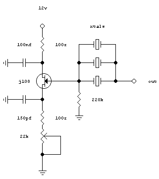
The
resulting circuit was the one shown below. Note that the gate-source
capacitor is missing, and this is formed by the internal capacitance of
the j108, which is quite high. Also note, there is a capacitor missing
from the output of the oscillator to the ground, which is formed by the
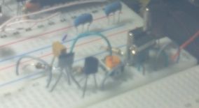
internal capacitance of my test probe. At the right photo, you can see
the circuit constructed onto a breadboard (that was used already by
another project). The picture is a bit blur, because I use a
polypropylenium glove box to make electronics inside, which is not 100%
transparent and the picture was taken from outside of the box. However,
you can
clearly see the one active device and the three crystals in place.
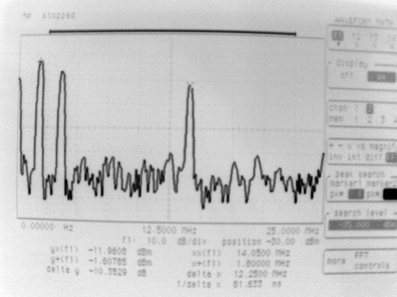
The results are shown in the picture below, as measured on the FFT of an HP54520A. The first signal is at 160m, and the third at 20m. If I can remember well, at the time the photo was taken, the second signal was at 40m, but on the scale it appears to be at 80m more likely. Anyway you get the idea.
On
the FFT, the fundamental of each crystal can be seen and all of them appear
at the output of the oscillator simultaneously. However, as I expected,
the oscillator gain, needs to be set up (22k trimmer) so that higher gain crystals do
not "take up" so much gain, because then, some lower gain crystals
could not produce output. However, when the gain is set to be less, the lower
gain crystals may not oscillate at all. So, the whole process it is a balance between gain
and output power. Because of it's circuit topology, the oscillator output is clean (no measurable harmonics) and all
3 carriers appear at the output at the same time. Such an oscillator, is characterized by it's very low distortion and phase noise. I
have succeeded in connecting up to 3 crystals in frequencies that are far apart. I have not
tested this, but I suspect if the crystal frequencies are too close,
they would interlock.
I have also tested the circuit at other frequencies (eg. 7MHz, 10MHz, 14MHz). The max number of crystals it could accept, was 3. After that, some crystals refused to produce output. The 22k trimmer had to be reset for every new crystal inserted in the circuit, so that all crystals could produce output simultaneously. Of course the output signal level of each crystal was not the same. To compensate that, I initially put a series variable capacitor with each crystal (not shown in the schematic above), which alters it's frequency a bit, but more importantly alters its output level (less coupling). This allowed to lower down the higher output signals, so that all three signals to appear at the common output the same level.
I have built the whole thing into breadboard, and tested on 1M and 50R
on FFT, although 50R is loading it too much, but it still works.
I was
satisfied my experiment was a success, but I could not initially figure out the reason why
this oscillator could oscillate at more than one frequencies
simultaneously. So I asked on a forum
if someone could explain this. A few kind people, tried the experiment
unsaccessfully and came up with reasons why such an idea does not work.
However, no one could explain why it worked for me. The result from
this conversation was that they started to get
suspicious about my honesty in this experiment, so I felt I should not
ask for more. For a few days wondered why it worked for me and not for the others.
Eventually I solved the mystery around this oscillator. It seems that it does work indeed, like I have initially predicted! I took the oppinion of an expert engineer from Wenzel Associates and also Hans G0UPL, was kind enough to try the circuit successfully on his page. This, confirmed that my circuit works. The problem in cases the circuit did not work, was probably crystal activity differences. The limiting caused by the "stronger" crystal will kill the gain sufficiently that the others don't start. Sometimes engineers actually have to fight the phenomenon when using SC-cut crystals that have a strong activity only 10% above the desired mode. However, I used cheap common AT-cut crystals.
Probably,
a better way (not yet tested) to achieve the same output levels for all
frequencies and to make the oscillator oscillate at all frequencies (instead of series capacitors with the crystals),
is to observe which crystal is oscillating and then add series
resistance to kill it's activity a bit, on the order of 10's of ohms.
Another crystal should come alive and eventually series resistors in
the right crystal legs should allow for fairly equal outputs.