How to read/program the PIC
Programming the PIC in Assembly language is split into a number of procedures:
-
First you have to write the program for the PIC. This is an ASM file that can be edited using any text editor you like. An example of such an editor is Notepad2.
-
Then you must assemble (compile) the program using a suitable assembler. This will produce a HEX file, which is the executable file for the microcontroller. A well known assembler is the MPASMWIN.
-
Finally, you must use another software and a suitable programmer hardware, to burn this HEX file into the microcontroller's memory. I provide two such software/hardware solutions below in this page.
If you do not want to have many programs you may consider the official freeware software of Microchip which is MpLab IDE which combines the code editor, the assembler, the burner, the reader and some debugging utilities into a single package. However, if you do not want to install many files into your computer (latest version requires java), I suggest you use the standalone software provided above.
Note, if you are interested only in programming the PIC16F84A, my other page may be useful to you.
To extract the hex file out of the microcontroller you usually use the same software and programmer, to read the data into a HEX file. A note here, some modern microcontrollers support code protection. If the author of the program has chosen to protect it's HEX code against copying you will be unable to correctly extract the HEX file out of the microcontroller. There may be some ways to cope with this, but let's talk about the official way.
Below are free solutions (software and hardware) on how to burn HEX files into different PICs and read HEX out of them. The hardware and software are almost universal parallel port programmers (LPT or as known, printer port) for a variety of Microchip Midrange Microcontrollers.
Programmer solution 1
The original programmer and software can be downloaded here. I have chosen to use the P16PRO for DOS, software ver 3.64, September 2000 including freeware licence key from http://www.picallw.com. P16PRO software for DOS works also under WINDOS 3.1 and WINDOWS 9x. The author has released also a newer windows version available here with more devices supported.
Supported microcontrollers (based on the device.ini):
PIC16F83,PIC16CR83, PIC16C84,
PIC16F84, PIC16F84A, PIC16CR84, PIC16F870, PIC16F871, PIC16F872, PIC16F873,
PIC16F874, PIC16F876, PIC16F877, PIC16C505, PIC12C508, PIC12C508A, PIC12C509,
PIC12C509A, PIC12C518, PIC12C519, PIC12C671, PIC12CE673, PIC12C672,
PIC12CE674, PIC14000, PIC16C52, PIC16C54, PIC16C55, PIC16C56, PIC16C57,
PIC16C57C, PIC16C58, PIC16C554, PIC16C556, PIC16C558, PIC16C61, PIC16C62,
PIC16C62A, PIC16C62B, PIC16CR62, PIC16C63, PIC16C63A, PIC16C64, PIC16C64A,
PIC16C64B, PIC16CR64, PIC16C65, PIC16C65A, PIC16C65B, PIC16C66, PIC16C67,
PIC16C620, PIC16C620A, PIC16C621, PIC16C621A, PIC16C622, PIC16C622B,
PIC16CE623, PIC16CE624, PIC16CE625, PIC16C710, PIC16C71, PIC16C711, PIC16C712,
PIC16C716, PIC16C72, PIC16C73, PIC16C73A, PIC16C73B, PIC16C74, PIC16C74A,
PIC16C74B, PIC16C76, PIC16C77, PIC16C717-18PIN, PIC16C717-20PIN, PIC16C770,
PIC16C771, PIC16C773, PIC16C774, PIC16C745, PIC16C765, PIC16C923, PIC16C924
Following PICs have 16bit word
PIC16C715, PIC16C642, PIC16C662
Also, you can simply add new devices by changing DEVICE.INI file accordingly (you must enter program size, data size, fuses type and algorithm type).
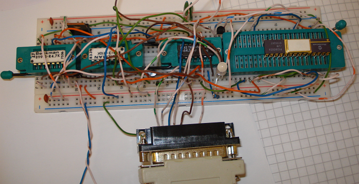
Above, is my implementation of this programmer on a breadboard, messy but it works fine. I have used resistor networks instead of resistors. Here, I have just programmed a PIC16C62A/JW, with the relevant firmware, that is used to make the programmer shown in the solution 2 below.
Programmer solution 2
Apart from PIC16PRO, the author has also released another version of hardware and software which is called PICALL. It supports more PIC microcontrollers and also some AVR and SX microcontrollers, as well as 24xxx EPROMs and it is available here (DOS) and here (Windows). In order to operate, this programmer requires also firmware to be burned on a PIC16C62 or a PIC16F72. The author sells this firmware so I am not allowed to distribute it here, but if you need pre-programmed chips I will be happy to order them for you.
So how can you burn the firmware into the PIC in order to make the PICALL programmer? Well, you could make the PIC16PRO programmer and use this to program the PIC16C62 or the PIC16F72. Then you can upgrade it to the PICALL programmer. This is exactly what I have done in the picture above.
The Windows version of the
software can work on Linux too. For running PICALLW under LINUX you need a
"WINE" windows emulator that works on
Linux and some configuration to be done, which is described below.
Modify the related part of the config file for wine (it is named config and is
in the .wine directory) to look like this:
[ppdev]
;; key: io-base of the emulated port
;; value : parport-device{,timeout}
;; timeout for auto closing an open device ( not yet implemented)
"378" = "/dev/parport0"
"278" = "/dev/parport1"
;"3bc" = "/dev/parport2"
[spooler]
"FILE:" = "tmp.ps"
"LPT1:" = "|lpr"
"LPT2:" = "|gs -sDEVICE=bj200 -sOutputFile=/tmp/fred -q -"
"LPT3:" = "/dev/lp3"
[ports]
"read" = "0x779,0x379,0x278-0x27a,0x280-0x2a0,0x378-0x37f"
"write" = "0x779,0x379,0x278-0x27a,0x280-0x2a0,0x378-0x37f"
One last thing: it has to be run as root in order to access the hardware.
I will post some more information on my implementation of this programmer as soon as possible.
How to erase the EPROM based PICs
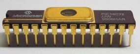
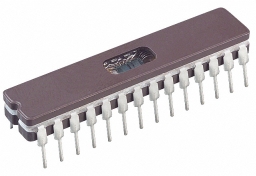
The programmer and software you use to program the PIC, can be most of the times used to erase it. The only exception to this, is the EPROM-based PICs. You can easily identify an EPROM-based PIC by noticing the little transparent window on top of it, which allows the chip die to be seen.
The EPROM-based PICs can only
be erased by pointing a UV-C radiation source to the chip die through the
transparent window of the chip. This is normally done with a device that is
called an EPROM eraser. An EPROM requires a specific frequency of UV 253.7
nanometers (2537 angstroms) to be erased. In fact the high frequency UV light
used will not pass through plastic or most glass. To pass this light, the
transparent window in the microcontroller is made of quartz crystal. The
correct frequency of a light source alone won't guarantee proper
microcontroller EPROM erasure. The intensity of the light source combined with
the distance from the light source determines the intensity of the exposure.
Light intensity varies inversely with the distances from the source. (The
longer the distance the lower the intensity of the light.) You will find that
the closer the microcontroller is to the light source, the faster it's EPROM
will erase. The chip manufacturer tell us, "the EPROM should be 1" from the
light source with an intensity of 12mW/Cm2". The manufactures state a 1"
distance to ensure that the light intensity is even over the entire EPROM,
defused, with no shadows over any part of the EPROM silicon. (Yet, some have
successfully used a 1/2" distance to speed their prototype work.)
Besides bulb to chip distance, bulb age also effects exposure time. Be aware
of the age of the microcontroller EPROM technology you are erasing. Older 1.3
micron technology takes longer to erase than .7 micron technology. With all
these variables, the best way to determine exposure time is to run an
empirical exposure test. First, expose the microcontroller for 1 minute and
test for erasure. If it is not erased, expose it again for another minute.
Keeping track of the total exposure time, repeat this process until it is
erased. Now take the total time and multiply by 1.5. For example, if it takes
3 minutes we should use a 4.5 minutes exposure time to ensure good erasure
without over erasing. Remember if you leave a microcontroller in the eraser
too long, it can remain erased forever and will no longer program.
Every time a microcontroller EPROM is programmed and erased it wears out a
little. Erasing cycles will slow down access times, but this is usually of no
consequence unless you erase them an extreme number of cycles or for an
excessive exposure time. An EPROM with slow access time, may still program and
work fine on a programmer, but beware that the programmer does not require or
test for a fast access time. A worn out EPROM may program correctly yet fail
to work if fast access time is required.
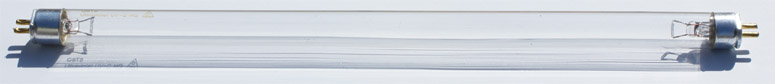
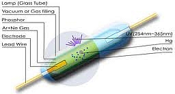
Home made EPROM eraser
A home made EPROM eraser can be made using a germicidal light bulb. Germicidal light bulbs are made of transparent quartz glass (instead of ordinary fluorescent bulbs) to allow the UV-C radiation to pass through it. Germicidal light bulbs used in hospitals for sterilizing equipment by killing germs. Germs are living cells. We are also made of living cells. Read carefully and follow the safety instructions that come with EPROM erasers and light bulbs.

UV-C radiation is harmful to the eyes and skin. You are not likely to go blind from accidentally looking at the light for few seconds, but germicidal lamps should only be operated in a safety-interlocked enclosure, a lightproof box. Two examples of EPROM eraser projects can be found here and here. You can also make an inverter and drive the tube from 12v, there are some projects on the net about how to do this.
My personal approach was to use the inverter solution, even though more expensive. The main advantage is that it operates from 12V and it does not heat the tube filaments, so the tube should last longer. It also produces less heat during operation. It works by applying a high voltage to the tube terminals and thus ionizing the gas inside the tube to produce radiation. For the tube, you can use g4t5 (4W), g8t5 (8W) or greater wattage tubes by connecting each terminal of the tube to the high voltage. It does not matter which pin of the tube terminal you connect the high voltage, since you are using the tube in cold-cathode mode. In my case I managed to find a commercial cold cathode designed tube, so I used this one.
I will post some more information on my implementation of the microcontroller EPROM eraser as soon as possible.