Universal, very low distortion, HF broadband crystal oscillator
please ask for KIT availability!

+12dBm
max, 160m - 10m very low distortion (all harmonics at least -40dBc) XO
requiring only the crystal to be changed for covering different
frequencies.
This is one of my best
designs so far. Using
common components, a
superior oscillator can be built, useful as a test oscillator for the
lab, as a driver for HF transmitters and receiver mixers etc. I
wanted a universal oscillator that could oscillate at all HF bands
without changing any components apart from the resonator. This would
save cost and pain, for having one circuit made for each band. Also,
This oscillator can oscillate at any frequency between bands as well,
not only inside the ham bands. Moreover, the oscillator is cheap and
easy to
build and it has very low distortion (harmonics) at all bands.
Combining these characteristics is very difficult and I have not seen
such a design posted elsewhere. I have been testing this circuit for
quite a long on FFT and I have done quite a few refinements to conclude
to this final version.
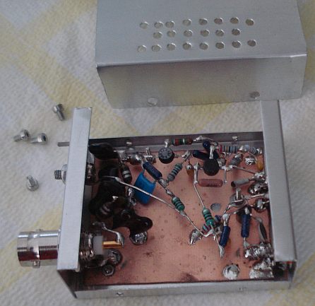
All coils (LPF and chokes) are molded types +/-10% tolerance or better.
The 200nH coil, is composed from two 100nH in series. All these three
coils in the LPF, should be aligned in a 3D perpendicular way, if no
shielding is used between them, to minimize mutual inductance. That is,
the first coil should be perpendicular to the second (X-Y axis) and the
second coil must start after the end of the first. The third coil
should be perpendicular to the second coil and starting from it's end
(Y-Z axis), but also perpendicular to the first coil (X-Z axis). The
LPF capacitors are silver mica types 1% tolerance. The 82pF and 150pF
capacitors near the JFET, must be NP0 types.
The 22k trimmer, is used to set the output level of the oscillator, for
each new crystal that is inserted. The size of the trimmer must be
small and it must be kept close to the JFET. Set this trimmer for
+12dBm at 50 ohm maximum output level, if you want the harmonics to be
kept low (at least -40dBc). In most frequencies you can get more
output, but the harmonics and the intermodulation products are
increased considerably at higher levels.
Both crystals and ceramic resonators/filters can be used in the
oscillator with similar performance. The two BFR96S transistors are
getting extremely hot (especially the
final one), so leave some space for them, for passive air cooling.
If you want constant output level and frequency changing by the flip of
a switch, install each crystal and it's corresponding trimmer, onto
each position of a stereo rotary switch and set this trimmer to the
desired output level for that crystal.
If you want constant output level for each crystal inserted but without
using many trimmers, try an ALC circuit. ALC has been tried with
success, by replacing the 22k trimmer with a vt43n1 LDR and pointing a
light source onto it (LED or better a low current incadescent bulb)
driven from
the output of the oscillator through a directional coupler and after
some amplification and rectification.
Back to main site