by SV3ORA
Built on 2011
HF all-band tuneable bandpass filter
by SV3ORA
Built on 2011
A front-end band-pass filter is always very important for the radioamateur. If you are really serious about RF you will eventually need a filter at the input of your receiver or at the output of your transmitter. On the transmitter side, a low-pass filter is only needed, to cut out the higher frequency harmonics of the transmitter but on the receiver side, a band-pass filter is needed, to cut out both the lower and higher frequencies and leave only the band of interest to be passed through it. Thus, a band-pass filter can be very useful in both receiving and transmitting purposes.
The purpose of an RF front-end band-pass filter plays also another great role on the receiver. It ensures that the front-end mixer of the receiver will not be overloaded by strong out-of-band signals. This is very important in direct conversion receivers. As far as concern superhet receivers, many well designed such receivers, include an internal RF front-end filter which "follows" the local oscillator signal and it allows only a certain band to pass through it, dependent on the local oscillator signal. For the superhets that have not this option, an RF front-end band-pass filter is a must too.
Making an all band HF band-pass filter can be tricky. The most widely used approach in commercial equipment, is to have many single-band resonant circuits and switch them to cover the HF amateur bands. There is nothing wrong with this approach, apart from cost and complexity of the final structure. Also, it may be difficult to easily alter the response of the filter on the fly, but altering the RF front-end filter is an option that very few commercial equipment have.
In my approach, instead of using multiple resonant circuits, I use just a single one, and alter the components values respectively to cover the whole HF. This has the advantage of low cost, easier construction and the filter response can be varied in different shapes. This filter is more difficult to tune on the fly though, so a predefined tuning-list is always helpful. This means that for each band, you have to tune your filter based on values taken from a predefined list. You can make your filter respond the way you want in each band, using a spectrum analyzer and a noise source in order to retrieve the filter response. Then you measure the readings of the filter components and switches and you write them down in a list. The next time you want to tune to this band just follow the list and re-tune your filter. Hopefully the only difficult parts to tune on this filter are the variable capacitors, but this can be easily solved by the use of micrometric knobs or verniers.
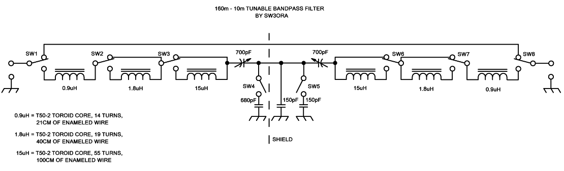
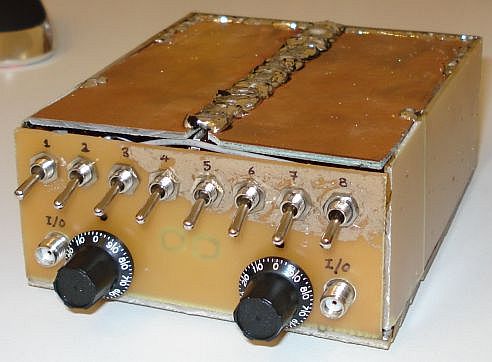
The band-pass filter is composed of a low-pass and a symmetrical high-pass one, connected in series and completely shielded from each other. If a symmetrical band-pass response is needed then double switches and dual-gang variable capacitors can be used to tune the "symmetrical" parts on each side (for example SW1 and SW8, SW2 and SW7 etc.), which minimizes the amount of tuning that must be done. If a variable response filter is desired though, you have to use single switches and separate variable capacitors and tune them independently. In the latest case, better shielding is ensured between the low-pass and the high-pass filter, due to the separate placing of the components.
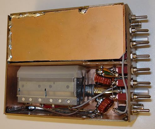
Shielding is very important in filters. The filter box is made out of PCB sheet, which is easy to cut solder and shape. The low-pass and high-pass filters are completely shielded in their own enclosures made out of PCB material and the variable capacitors have been isolated from the ground (PCB box).
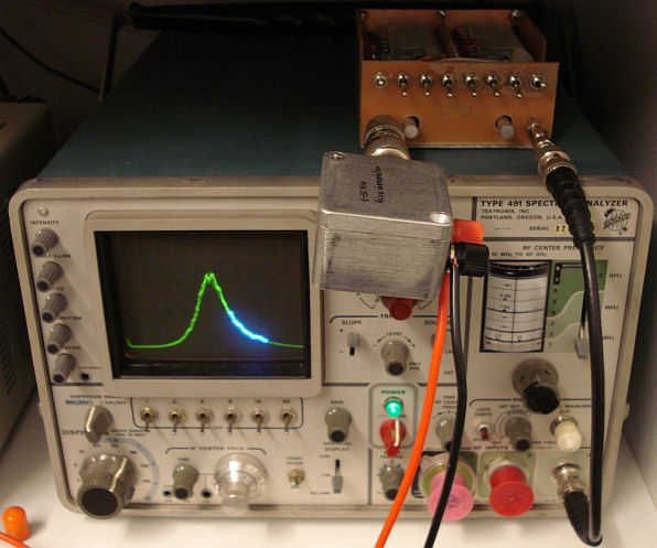
The filter has been tested using the spectrum analyzer and performed as designed throughout the HF bands. The picture below shows an example of the filter response on 23MHz on an analogue spectrum analyzer.
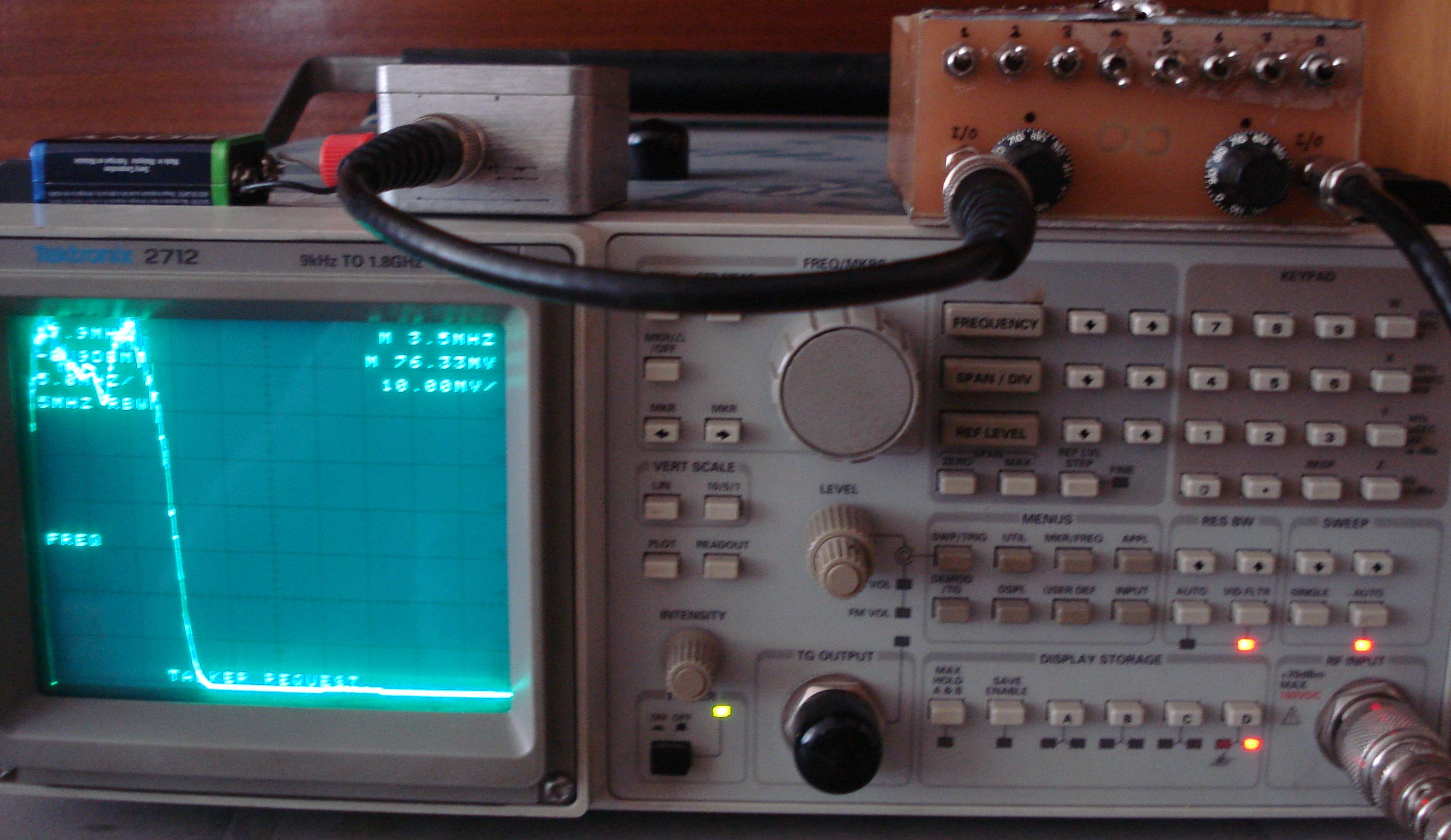
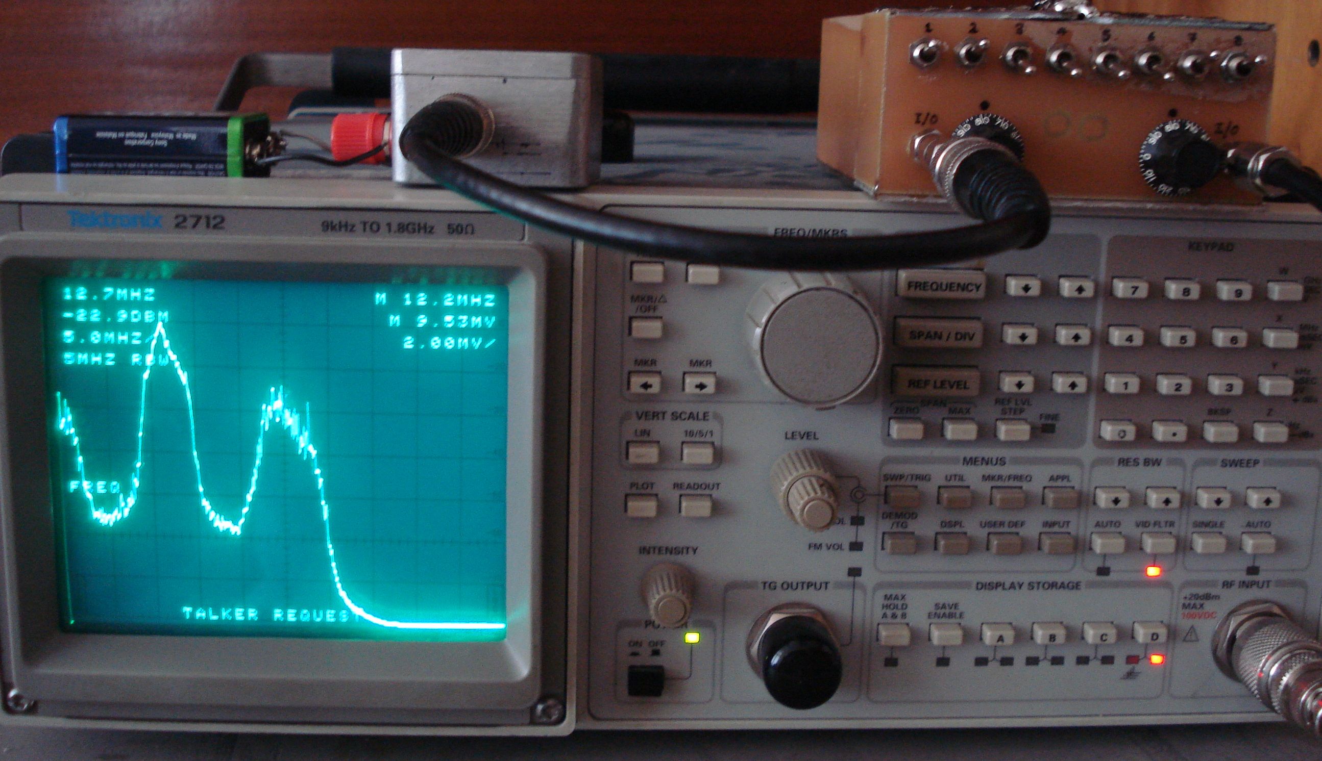
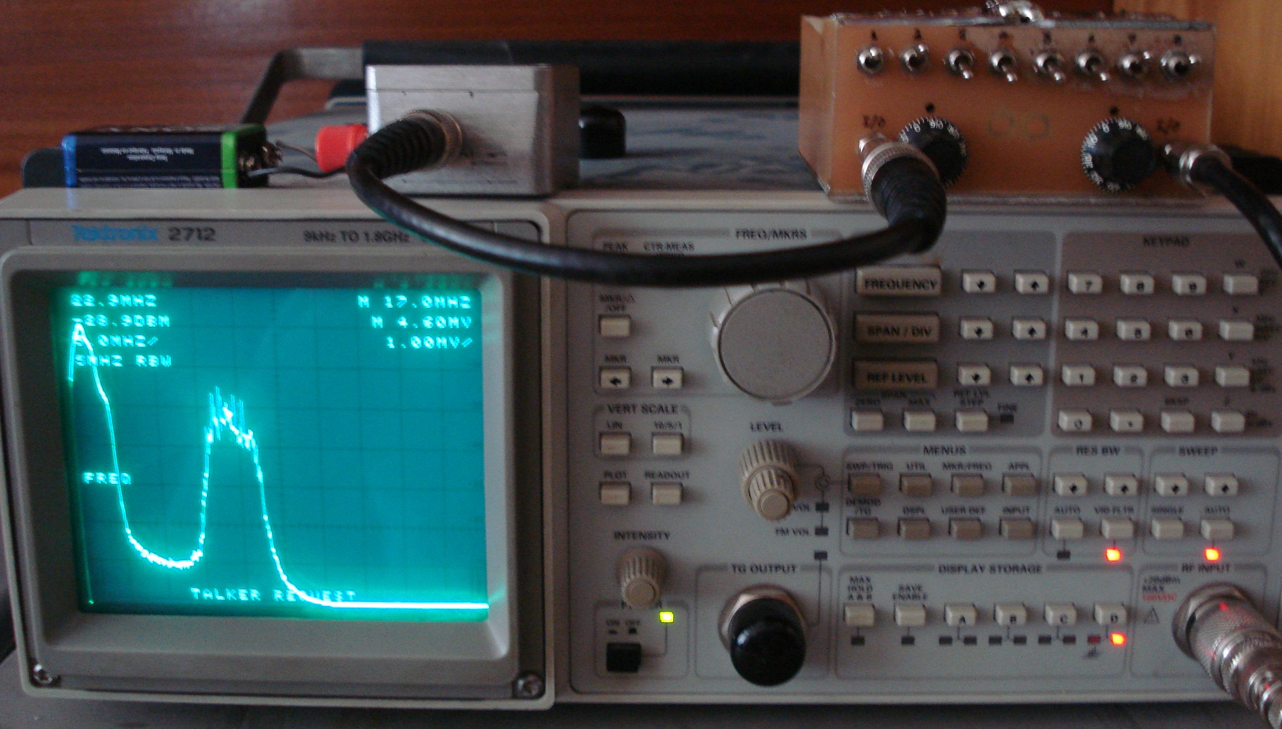
Below, there are pictures of the same filter tested on a digital spectrum analyzer. Click on each picture to enlarge it and to see the filter curve response in different switches and capacitor settings. This will help you create the filter settings matrix. Please note, I have not used the same spectrum analyzer settings on all frequencies. Also, look only at the right hand side signal and ignore the middle and left ones. The middle one is probably the spectrum analyzer local oscillator and the left one is the image. When the frequency is below about 2MHz the right and the middle signals overlap. The filter can tune from 1.4MHz to 30MHz, as designed.