
Vibration
activated
LED charge pumps
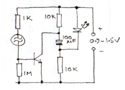
This circuit will momentarily light up a 3V LED from a 1.5V battery, when the vibration switch at the base of the transistor closes. The circuit works like this:
The capacitor charges slowly through the two
10K resistors until it reaches battery voltage. The LED has insufficient voltage
across it to conduct and the transistor has no bias current so the circuit stops
drawing any current (except leakage). When the vibration switch closes, it
passes enough current to saturate the transistor which brings it's collector
voltage close to 0V, this makes the negative side of the capacitor go to the
battery voltage below 0V so the total voltage across the LED is
momentarily twice the battery voltage making it flash. For the LED to light up, the capacitor must be
charged enough and the vibration switch must be closed.
The 1M resistor is just to desensitize the input to static and help to
reduce transistor leakage, it might be possible to omit it. It may also
be necessary to add a resistor in series with the LED to limit it's
current, especially if a higher value capacitor is used. A transistor
with low VCEsat will work best, if it's one with low gain the bias
resistor can be reduced down to maybe 100 Ohms. Note that the circuit
will not be able to light up a UV-led that requires more than 3v from a
rechargable 1.2v battery (2x1.2v=2.4v).
For the transistor, I used a PN2222 but only because I had them to hand. The best transistor is one with lowest VCEsat. That means the one with lowest collector voltage when biased to saturation.
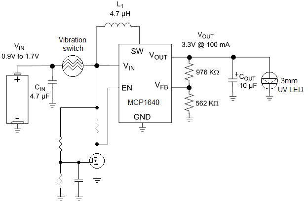
Another (incomplete) similar circuit is shown above. This has the advantage that no significant current is drawn from the battery after the first few LED pulses. The principle is to generate a one-off pulse at the EN pin when the vibration sensor closes. As the gate capacitor charges it makes the MOSFET conduct, pulls the EN pin low and shuts down the MCP1640. There are some problems though that need to be resolved. The MOSFET is unlikely to conduct with a Vgs of less than 0.9V and the time it takes to charge the gate capacitor would probably be less than the sensor switch is closed for. So careful choise of the RC components is needed. The vibration sensor is a standard "weight inside a spring" type which produces pulses typically < 1mS. Given the time constant at the gate pin and the time it takes to 'pump up' the voltage, there may not be enough time to generate enough voltage for the LED to light. You have to experiment if you want to use this circuit.
Here
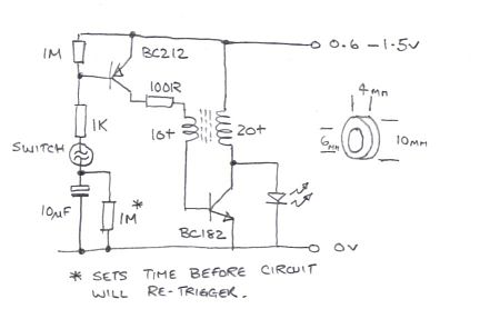
is another similar circuit based on a joule thief to increase the
voltage. Using the same UV LED (Vf = 3.3V) it gives a bright flash at
0.9V supply with a 'just works reliably' supply voltage of 0.65V. I
tried it up to 1.5V but not higher, it should be OK up to about 2V
before the LED starts to draw it's own current.
I salvaged the ferrite core from a broken CFL, it seems to be used
quite commonly in many different types but I do not have it's
specifications or part number. You can get a slight increase in
brightness by adding a 100nF capacitor from the junction of the 100R
resistor and transformer to ground but it probably isn't worth fitting
and it could risk the circuit self-biasing, in other words not shutting
down after it has been triggered. It was OK for me but make sure it
stops drawing current after a few seconds if you add it to your build.
Increasing the 1M timing resistor will make it take longer to
re-trigger but don't drop it below about 220K as it pass enough current
to turn the first transistor on whenever the switch is closed.
The first transistor is PNP and the flash occurs when it passes base current in
to the charging electrolytic capacitor. The resistor across this
capacitor is to discharge it again so it is ready for the next time the
switch closes.
Efficiency isn't really important here but the battery life is. The
circuit draws negligible current when not being used (< 1uA) and a
higher current peaking at about 30mA as the LED flashes. The average
current over a long period is very low. In reality, it actually is
quite efficient, I did not calculate it but I would guess while the LED
is lit, it would be >50%. The power needed to light the LED is
going to be about the same which ever way you do it but this method
avoids the need for active timing circuits which inevitably draw
current all the time and therefore reduce overall circuit efficiency.
The flash is quite bright and lasts about 0.5 second.
I used transistor to hand, but the types are not critical, the highest voltage on the circuit is only 3.3V. As before, you will get more output if the VCEsat of the second transistor is as low as possible because it is effectively unavailable as usable voltage. It should work OK with 2n2222 and 2n2907 as well, but if you have others, it would be worth experimenting with the second (NPN) transistor to see which works best.
The picture
below, shows another more elegant circuit. A low current monostable and
an active 'inhibit' circuit is added, to prevent re-triggering too
soon.
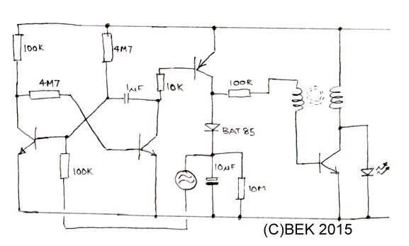
The
oscillator and PNP switch works as before, but the first two
transistors form a monostable circuit. In 'idle' state, the collector
of the first transistor is low and the second transistor is high
(keeping the switch OFF). When the first base is pulled low, the
monostable changes state until the 1uF capcitor discharges then it
returns to idle condition again, during this time the PNP switch is ON
and the LED lights. When the PNP switch is ON, it charges the 10uF
capacitor through the diode (must have low Vf) and raises the voltage
across it too high to retrigger the monostable again. When back in idle
state, the 10uF capacitor slowly discharges through the 10M resistor
until it is close enough to zero to be useful as a trigger voltage
source again.
1uF sets the pulse duration
10uF/10M sets the inhibit time.
It works fine on 0.9V but I found if I increased the supply to more
than about 1.5V there was a tendency for the oscillator to run by
itself. This is because the diode and capacitor 'close the loop' in the
base side of the transformer and keep the bias running in the
oscillator transistor. If your does that, the only simple solution is
to reduce the turns on the secondary winding to drop the gain a little.
An
interesting side effect of the inhibit circuit is if you keep the
switch closed (unlikely in real life) it turns the monostable into an
astable circuit and the LED will flash at inhibit rate. If all is well,
that should be > 5 seconds or so. I used the same transformer as the
previous design. The values I used were just components I had to hand,
it worked with them but they are not critical. The NPN transistors were
all BC548s. At very low voltages it isn't stable but the prototype
still functioned at 0.59V!
I measure the current in idle state of the monostable as:
8uA at 0.9V
11.9uA at 1.2V
14.5uA at 1.5V
For best results, the diode mast have low Vf. An example of such diodes is shown here.