
Energy Harvesting and
Efficiency
Experiments with low powered and energy efficient systems
by SV3ORA
This page shows my series of experiments that demonstrate low powered and efficient systems, as well as ways to provide energy out of different environmental sources.
Joule thief
The Joule thief, is a minimalist self-oscillating voltage booster that is small, low-cost, and easy-to-build. The circuit uses the self-oscillating properties of the blocking oscillator, to form an unregulated voltage boost converter. As with all power conversion technology, no energy is actually created by the circuit (in accordance with the law of conservation of energy). Instead, the output voltage is increased at the expense of higher current draw on the input. As a result, the amount of power entering the circuit is the same as the amount leaving, minus the losses in the conversion process.
The circuit works by rapidly switching the transistor. Initially, current enters
the transistor base terminal (through the resistor and secondary winding),
causing it to begin conducting collector current through the primary winding.
This induces a voltage in the secondary winding (positive, because of the
winding polarity) which turns the transistor on harder. This
self-stoking/positive-feedback process almost instantly turns the transistor on
as hard as possible (putting it in the saturation region), making the
collector-emitter path look like essentially a closed switch (since VCE will be
only about 0.1 volts, assuming that the base current is high enough). With the
primary winding effectively across the battery, the current increases at a rate
proportional to the supply voltage divided by the inductance. Switch-off of the
transistor takes place by different mechanisms dependent upon supply voltage.
The predominant mode of operation relies on the non-linearity of the inductor
(this does not apply to air core coils). As the current ramps up it reaches a
point, dependent upon the material and geometry of the core, where the ferrite
saturates (the core may be made of material other than ferrite). The resulting
magnetic field stops increasing and the current in the secondary winding is
lost, depriving the transistor of base drive and the transistor starts to turn
off. The magnetic field starts to collapse, driving current in the coil into the
light emitting diode (raising the voltage until conduction occurs) and the
reducing magnetic field induces a reverse current in the secondary, turning the
transistor hard off.
At lower supply voltages a different mode of operation takes over: The gain of a
transistor is not linear with VCE. At low supply voltages (typically 0.75v and
below) the transistor requires a larger base current to maintain saturation as
the collector current increases. Hence, when it reaches a critical collector
current, the base drive available becomes insufficient and the transistor starts
to pinch off and the previously described positive feedback action occurs
turning it hard off.
To summarize, once the current in the coils stops increasing for any reason, the
transistor goes into the cutoff region (and opens the collector-emitter
"switch"). The magnetic field collapses, inducing however much voltage is
necessary to make the load conduct, or for the secondary-winding current to find
some other path.
When the field is back to zero, the whole sequence repeats; with the battery
ramping-up the primary-winding current until the transistor switches on.
If the load on the circuit is very small the rate of rise and ultimate voltage
at the collector is limited only by stray capacitances, and may rise to more
than 100 times the supply voltage. For this reason, it is imperative that a load
is always connected so that the transistor is not damaged. Note that, because
VCE is mirrored back to the secondary, failure of the transistor due to a small
load will occur through the reverse VBE limit for the transistor being exceeded
(this occurs at a much lower value than VCEmax).
The transistor dissipates very little energy, even at high oscillating
frequencies, because it spends most of its time in the fully on or fully off
state, thus minimizing the switching losses.
The switching frequency in the example circuit opposite is about 50 kHz. The
light-emitting diode will blink at this rate, but the persistence of the human
eye means that this will not be noticed.
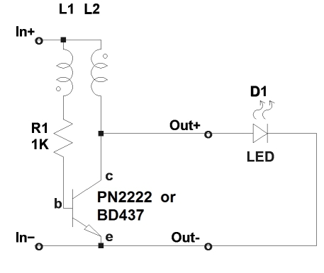
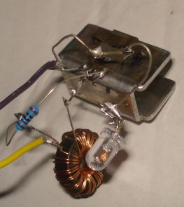
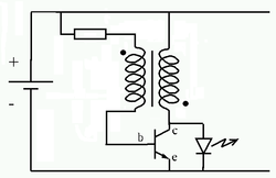
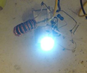
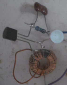
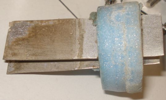
Here is a practical implementation of the joule thief. The schematic diagram for this experiment, as well as the prototype built, are shown above. L1/L2 is a transformer wound on a FT50-75J toroid core. Wind 20 bifilar turns of 0.6mm enameled copper wire (diameter not critical) on the transformer and connect the end of the one winding to the beginning of the other (this connection point is then connected to In+).
You may use almost any small NPN transistor like the common PN2222. The oscillator starts reliably at about 0.5V. By experiment, I found that if using a power transistor like BD437, the oscillator was able to start at about 0.4V.
I have made another version of this circuit as well using a small ferrite bead and it worked fine too. Nevertheless, the use of a high permeability toroid like the FT50-75J in combination with a power transistor, should be able to provide much more current, although I have not practically verified this.
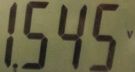
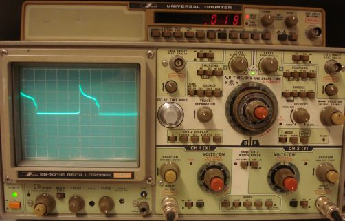
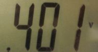
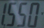
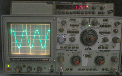
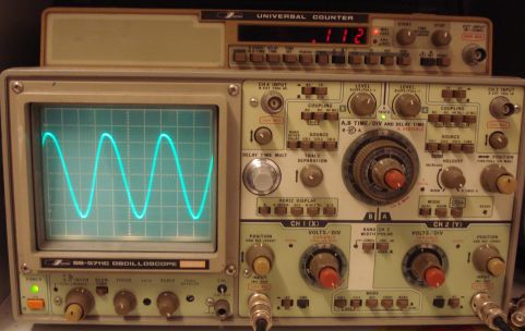
Using a BD437 in the prototype and a FT50-75J core, the results were good. At 1.5V the circuit oscillates at 22KHz and the LED shines brightly. Current consumption is about 60mA. Oscilloscope shows a square like waveform of about 4Vpp at this point.
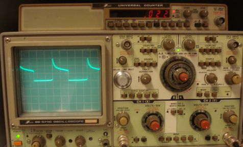
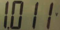
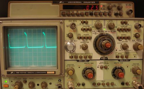
At 1V the circuit oscillates at 18KHz. Current consumption is about 50mA. Oscilloscope shows a more distorted square like waveform of about 3Vpp at this point.
At 0.4V the circuit oscillates at 25KHz and the LED shines much more brightly than the US Patent 4,734,658 circuit. Current consumption is about 10mA. Oscilloscope shows a low duration pulsed waveform of about 3Vpp at this point.
The circuit operates
at the lowest starting voltage of 0.4v in the picture below. The LED
shines much more brightly than the US Patent 4,734,658 circuit, but
also consumes much more current. The power transistor can easily
provide much more current than a small FET.
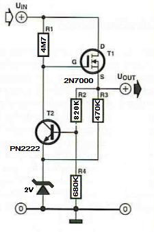
US Patent 4,734,658
This patent describes a low voltage driven oscillator circuit, capable of operating from as little as 0.086V. This is a far lower voltage than that at which the Joule Thief will operate. This is achieved by using a JFET, which does not require the forward biasing of a PN junction for its operation, because it is used in the depletion mode.
In field-effect transistors (FETs),
depletion mode and enhancement mode are two major transistor types,
corresponding to whether the transistor is in an ON state or an OFF state at
zero gate-source voltage.
Enhancement-mode MOSFETs are the common switching elements in most MOS logic
families. These devices are OFF at zero gate-source voltage, and can be turned
on by pulling the gate voltage in the direction of the drain voltage; that is,
toward the VDD supply rail, which is positive for NMOS logic and negative for
PMOS logic.
In a depletion-mode MOSFET, the device is normally ON at zero gate-source
voltage. Such devices are used as load "resistors" in logic circuits (in
depletion-load NMOS logic, for example). For N-type depletion-load devices, the
threshold voltage might be about -3V, so it could be turned off by pulling the
gate 3V negative (the drain, by comparison, is more positive than the source in
NMOS). In PMOS, the polarities are reversed. Depletion-mode PMOS are made for
ICs and are not generally available as discrete devices.
The mode can be determined by the sign of the threshold voltage (gate voltage
relative to source voltage at the point where an inversion layer just forms in
the channel): for an N-type FET, enhancement-mode devices have positive
thresholds, and depletion-mode devices have negative thresholds; for a P-type
FET, enhancement-mode negative, depletion-mode positive.
Junction field-effect transistors (JFETs) are typically depletion mode, since
the gate junction would forward bias if the gate were taken more than a little
from source toward drain voltage. Such devices are used in gallium-arsenide and
germanium chips, where it is difficult to make an oxide insulator.
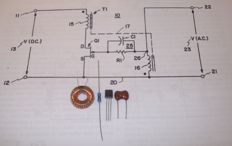
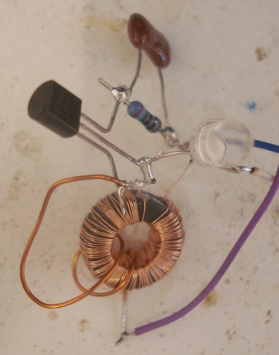
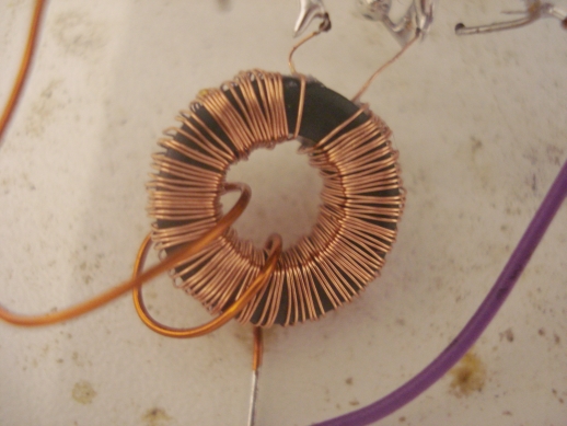
The schematic diagram for this experiment, as well as the prototype built, are shown above. I initially tried a J310 transistor for Q1. R1 was 10M and C1 was 100pF. T1 (17) was wound on a FT50-75J toroid core. T1 secondary (16) was built using 100 turns of about 0.16mm enameled copper wire.
T1 primary (15) was built using a few turns of 0.6mm enameled copper wire (diameter not critical). You can also use a small piece of insulated cable instead. The patent states that the transformer should be 1:100, but I initially tried 4 turns, then reduced this to 2 turns and then to 1 turn. The circuit worked at all these ratios, but I found the best LED brightness at 2 turns.
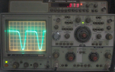
The results are astonishing. At 1.5V the circuit oscillates at 79KHz and the LED shines brightly (Not so bright than the Joule thief in the same voltage though. Maybe this is due to the low current capability of the J310). Oscilloscope shows a clipped waveform of 11Vpp at this point.
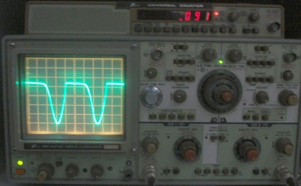
At 1V the circuit oscillates at 91KHz. Oscilloscope shows a clipped waveform of 9Vpp at this point.
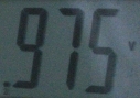
At 0.086V the circuit oscillates at 122KHz. Oscilloscope shows a clean sinusoidal waveform of 5Vpp at this point.
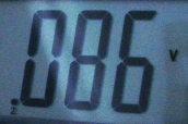
The lowest starting point of the oscillator is 0.086V. At this point the LED brightness is very low, as shown in the picture below.
I believe the lower
brightness of the LED at higher voltages, compared to the Joule thief,
has to do with the lower current capability of the J310. I have also
tried BF246C (same as BF247C), trying to get more current. It did not
work satisfactorily. The minimum starting voltage of the oscillator was
200mV and the brightness was almost that of the J310.
Update 20-9-2013
I tried a J108 today.
The oscillator starts at a minimum of 150mV instead, but at 150mV the
led shines much more brightly than with the J310. Also, as the input
voltage is increased, the LED is much more bright and now the circuits
brightness compares is like the Joule thief, but starting at a much lower
voltage.
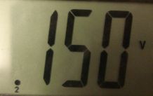

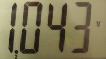
At 150mV the circuit
oscillates at 112KHz and it consumes about 10mA with the LED connected. Oscilloscope shows a clean sinusoidal waveform of 5.3Vpp at
this point. The LED brightness is much more than that of the J310 at the same voltage.
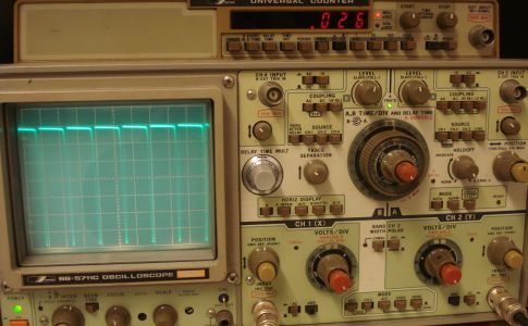
At 1V the circuit
oscillates at 26KHz and it consumes about 150mA with the LED connected. Oscilloscope shows a clipped waveform of 35Vpp at
this point. I have pulled up the top line to measure the spikes. The
spikes are on the negative portion of the signal. The top line is at 2.5v.
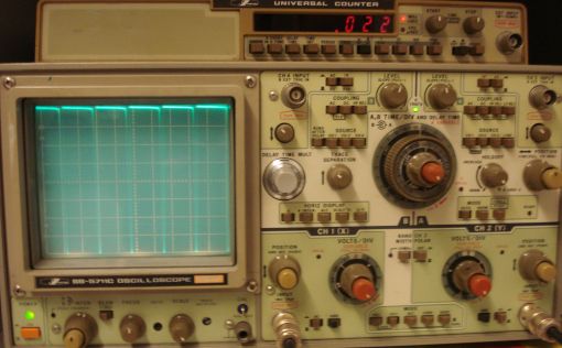
At 1.5V the circuit oscillates at 22KHz and it consumes about 200mA with the LED connected. Oscilloscope shows a clipped waveform of more than 40Vpp at this point. I have pulled up the top line to measure the spikes. The spikes are on the negative portion of the signal. The top line is at 2.5v.
At 0.7V the circuit consumes about 100mA with the LED connected. At 0.5V the circuit consumes about 80mA with the LED connected. At 0.3V the circuit consumes about 4mA with the LED connected.
Conclusion
This patent circuit is
absolutely fabulous. I would use the J310 in applications that require
a small current from an ultra low voltage source, like charging a
supercap slowly. If an input voltage of 70mV more can be tolerated and
if the source can provide enough current, I would definitely use the
J108, as it is able to provide much more current. The LED really shines
like the Joule thief circuit, but starting reliably at a much lower
voltage!
Micropower voltage regulator
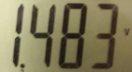
An old magazine article describes the operation of a small voltage regulator that has a very low current consumption. This means that most of the input energy is delivered to the output of the regulator. The regulator itself draws only about 14uA (I think that value refers to 5V output).
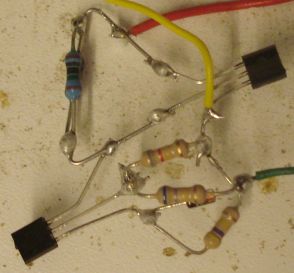
The schematic diagram
for this experiment, as well as the prototype built, are shown above. I
modified the schematic, so that the circuit can provide an output of
maximum 2.7V, enough to charge a 2.7V super capacitor at a safe voltage
level. I also used a 2V zener diode as a reference instead of a LED.
The output voltage never exceeds 2.7V as long as the input voltage is
below 18V. The measurements are shown below.
18V input gives 2.7V output (unloaded)
12V input gives 2.6V output (unloaded)
8V input gives 2.5V output (unloaded)
5.3V input gives 2.4V output (unloaded)
4.2V input gives 2.3V output (unloaded)
3.7V input gives 2.2V output (unloaded)
3.5V input gives 2.1V output (unloaded)
3.4V input gives 2.0V output (unloaded)
3.3V input gives 1.9V output (unloaded)
3.2V input gives 1.8V output (unloaded)
3.1V input gives 1.7V output (unloaded)
3.0V input gives 1.6V output (unloaded)
2.9V input gives 1.5V output (unloaded)
2.6V input gives 1.2V output (unloaded)
As it can be seen, the output voltage is not very stable and it depends
on the input voltage. Nevertheless, a large variation in the input
voltage, yelds to a much smaller variation in the output voltage, which
could make this regulator useful. Considering the measurements, I would
say this regulator is suitable for input voltages of more than 4V to 5V
or so.
Aluminum-air/Graphite, Sodium Hydroxide solution (NaOH) activated battery
Here is a practical approach for the building of a useable battery cell, that shows an acceptable performance. You can use this battery to power low powered electronics, using a step-up converter or more cells in series. Roughly describing the performance of the battery built, the unloaded voltage is on the order of 1.5V and the loaded on the order of 0.5V or so. Whereas this is a small-sized battery, a Joule thief inverter connected to it, can light up a LED for about 2-4 hours before a new solution needs to be added.
Aluminum-air batteries produce electricity from the reaction of oxygen in the air with aluminum. They have one of the highest energy densities of all batteries. Aluminum-air batteries are primary cells i.e., non-rechargeable. Once the aluminum anode is consumed by its reaction with atmospheric oxygen at a cathode immersed in a water-based electrolyte to form hydrated aluminum oxide, the battery will no longer produce electricity.
But why just simply buy a rechargeable battery instead of making one? First, this is all experimentation is about. Second, there may be cases where a battery needs to be stored for long time before used. Commercial rechargeable batteries (even Eneloops, but much less) suffer from self-discharging over time. This aluminum-air battery is activated only when the aluminum is dipped inside the solution.
Batteries can be made out of different things and they can be sophisticated or fancy. For a practical battery, not only the materials used have to be considered, but also a series of other parameters, like how to keep the electrodes in place, how to prevent accidental leakage of the solution etc. In either case, making a battery instead of buying one has only sense if it can be made quick, cheap and easily, and this includes the reusability and the cost of parts.
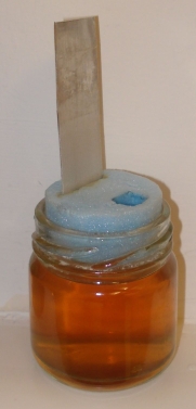
The pictures below, show a version of the battery made using salt water as a solution. This battery has a less voltage and current capability than the one made with NaOH solution. I have also tried vinegar/saltwater solution, which performed a bit better than salt water, but the ultimate solution I have found to date is the NaOH water one.
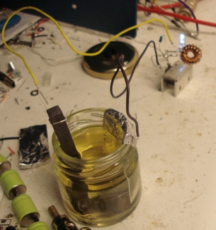
To make the battery, I used a tiny glass jar out of the kitchen. The size of the jar depends on the size of the electrodes you are going to use.
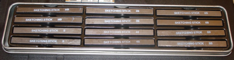
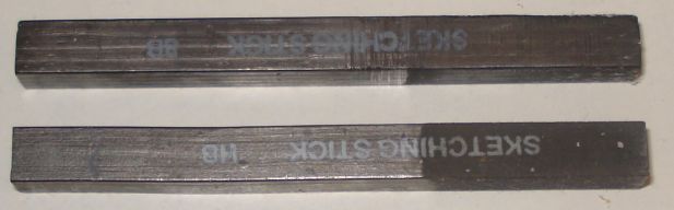
For the first electrode, I used a graphite square rod, taken out of these artists sketch sets. These sets cost about 2 Euros and they contain 12 rods, of different hardness. The one I have initially tried marked with an "B". There are others marked with 2B, HB etc, as shown in the next picture. These represent the hardness of the rod, because sketch artists want rods with different hardness. The measured resistance of all rods, varies from 2.5 Ohms to 12 Ohms from side to side. Alternative switching to different rods hardness for the electrode, does not seem to matter in unloaded voltage taken out of the battery. If you cannot find such a rod-set, you can burn out a pencil and when the pencil wood has been burned out, you will be able to take out the graphite rod without breaking it.
For the other electrode, I used a sheet of non-anodized aluminum. You can use
cheap aluminum foil from the kitchen, folded in shape, no problem. The main
reason I used a thicker sheet of aluminum instead of aluminum foil, was to
prevent it from too quickly get consumed. This way I do not have to replace the
sheet too often. Also, replacement is easier, as shown below. The carbon
electrode does not need to be very big, but for the aluminum electrode, the
bigger the better. I think this has to do with the current capability of the
battery.

To mechanically keep the battery stable, you can use a piece of cork or wood or styrofoam, like the ones used for home wall insulation. I prefer styrofoam, since it can be easily cut and shaped. I cut, in cylinder shape, a piece of styrofoam. The size of the cylinder must be such that when it is inserted onto the jar, it must be kept firmly there, preventing the solution from leakage.
Then I used a cutter, to cut a sheet-shaped hole of appropriate size through the styrofoam. Then I slip the sheet of aluminum into the hole, like shown in the pictures above. The advantage of slipping the aluminum sheet in and out of the jar, is that you can activate the battery whenever needed only. Also, I believe you can control the current this way! Activating the battery whenever needed only, is important in this kind of battery, because the reaction starts immediately after the aluminum sheet is dipped inside the solution, even if there is no current drawn or even if there is no graphite electrode dipped in the solution at all.
I see a good advantage on this. You can store your homemade batteries for a long time and use them whenever needed only. You can control the current by dipping in the aluminum sheet accordingly.
To mount the graphite electrode, I made a small hole on the styrofoam, opposite to the aluminum electrode hole. The spacing of the two electrodes does not matter much. I have chosen not to make the hole too tight, so that the graphite rod can slip in and out very easily without get scratched. I could leave the graphite rod continuously inside the solution (the graphite rod is not deteriorated by the electrolysis like the aluminum electrode does), but I have made it able to slip in and out, because I used the same hole on the styrofoam to fill-in the new solution or spill out the old one. Well, I could have used a third hole to do this, but I also liked the idea of being able to change graphite electrodes and try different ones.
So how tight this hole must be? Not too tight, to be able to slip in and out the carbon electrode, but also not too loose, to be able to keep the carbon electrode in place and prevent it to touch the aluminum electrode. A thicker cylinder styrofoam can help on this too.
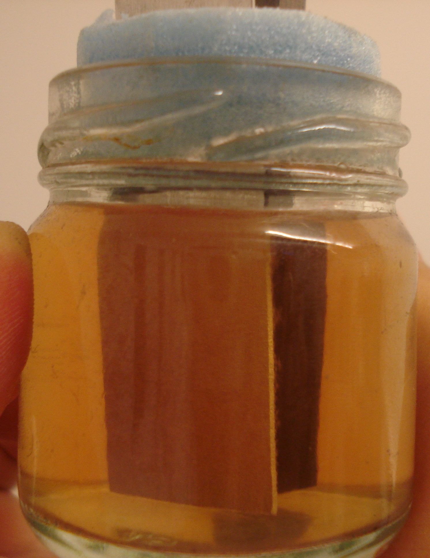
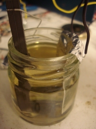
The picture above, shows the battery in action. If you click it, for full size, you may notice little bubbles (possibly hydrogen gas) that come out of the aluminum electrode, as the reaction takes place. Also notice that my NaOH solution has an amber colour instead of a clear white/transparent one that it should be. This is not because of the reaction, the NaOH solution I have used, has been previously used for some PCB etching work, so it has been a bit dirty.
Here, notes about how to make the solution...
The first tests were a big surprise to me. The battery worked good, the brightness of the Joule thief driven LED was very high in the first minutes, indicating a high voltage. After a few minutes the voltage dropped a bit and the LED is a little bit dimmer, but much brighter than the other battery designs I have tried in the past. This brightness keeps on up to about one hour or so and then the LED starts to dim even more up to about 11 hours, where the Joule thief barely oscillating. Just to mention, the two electrodes are about 4cm dipped inside the solution. I believe a bigger size battery will be able to provide more current.
To my surprise, the aluminum sheet had not been consumed much on the first complete run. The graphite rod was intact, with no signs of consuming or deposited material onto it. These were all at the first battery run. If the aluminum electrode was made out of kitchen aluminum foil, it might have been thickened too much and cut-off in pieces. But the aluminum sheet has been consumed a little and the look of it's surface was more or less like an anodized aluminum surface.
It seems that a thick aluminum sheet for the aluminum electrode will allow several runs of the battery, before it gets consumed. As long as the aluminum sheet has not been consumed, you can "recharge" the battery in minutes, by spilling the old solution and filling-in a new one. Then the battery can be reused again.
I use s small syringe to perform both operations, just to prevent the caustic solution to get things messy around. Warning, if not using gloves, at least use safety glasses when performing this operation, as the solution is caustic.
When I run a second
and a third run on the battery, by trying the graphite electrode 8B as
well as HB, I have noticed material deposited onto these electrodes
(right hand
side on the next picture). This material is probably hydrated alumina, from the
reaction of the battery. The material amount is less onto the
8B electrode. This material can be taken out by lightly
scratching the graphite. Note, I left the solution much longer inside
the glass jar after the battery has been discharged.
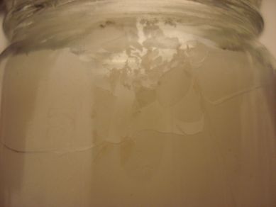
The glass jar had also deposited material when letting
the solution for much longer inside it, after the battery has been
discharged. This material is quite hard, but when rubbed it fleaks
apart, like shown in the picture below.
The aluminum electrode had also deposited material when letting the solution for much longer inside the jar, after the battery has been discharged.
Don't be confused about the two sheets of aluminum, I have tried it in order to increase the amount of aluminum inside the solution.
Next, I will try to see if removing of the old solution just when the battery is discharged, will avoid this material deposit on the electrodes and the jar.
A simple incandescent bulb
This is not an energy efficient experiment, but it is fun to see how simple home components can be used to make a light bulb. Maybe this could be used as an emergency light, if constructed properly and if enough power is available.
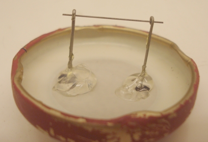
To make the bulb, I used a small jar and made two small holes on its cup. Then I passed two components leads through the holes and soldered them using hot silicon glue. The components leads were bended at the top, just enough to be able to hold a small graphite rod, which was taken out of a mechanical pencil refill.
Later on, I replaced these components leads with binding posts. The leads were getting just too hot and they melted the glue around them.
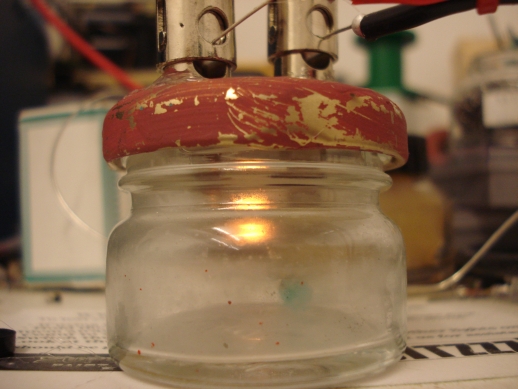
Above, is the result with the graphite rod used as a filament. The light lasts for a few tens of seconds, before the rod gets damaged. I tried to seal the jar using hot glue, so that no additional air gets inside, but with no success.
The next attempt to make an incandescent bulb, was to replace the graphite rod with a resistance wire. I did not have any resistance wire, but this can be easily found by ripping out a common wire wound resistor.
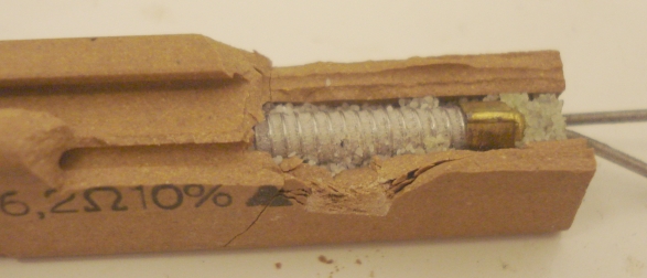
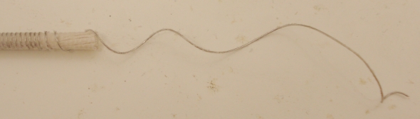
After taking off the ceramic material on the resistor, the resistance wire can be taken out and wound like a coil.
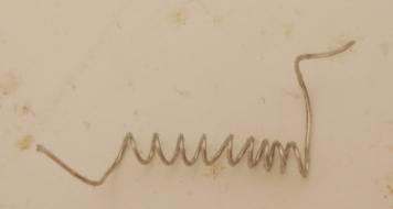
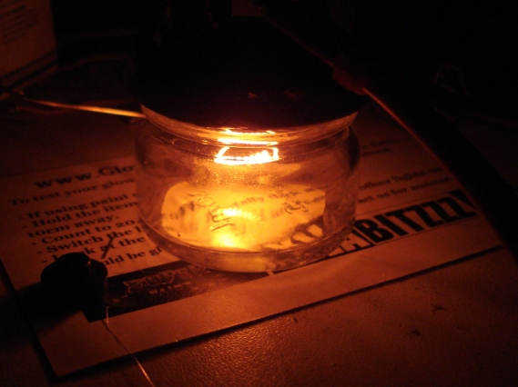
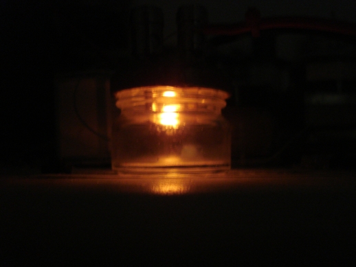
Above, is the result with the resistance wire used as a filament. The light lasts for a few minutes, before the wire gets damaged. I tried to seal the jar using hot glue, so that no additional air gets inside, but with no success. Even the binding posts get really hot when using the resistance wire.