easy40
A 14-components high-power transmitter to get you quickly on the air
please ask for KIT availability!

UPDATE 24-4-2020.
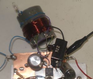
The above image shows more modifications. I have completely altered the
transformer to use air core and an additional winding essential for
tuning the transmitter when in the field. For the oldest version of the
transmitter, read this page below.
Introduction
QRP
is all about doing more with less. This is more than true, with the
construction of this cheap, small-size, keep-it-simple transmitter presented here. It
is just remarkable how 14 components can lead in so much output power,
that lets you commnicate with a big part of the globe, when propagation
conditions are right. From all my other constructions, this one stands
out in terms of simplicity in balance to the performance.
Following my instructions, the transmitter can be reproduced easily,
within hours. The result is always success, this is one of the circuits
that are not critical at all and a successfully working transmitter can
be reproduced every time. I have built this transmitter several times,
using similar components and it always worked. However the components
and the way of construction I present here, ensures stability and low
cost and guarantees that the transmitter will always meet the next
specifications:
Main carrier output power (excluding harmonics): 2.5mW-8W
(adjustable) at 50R
Band of operation: 40m
Output power adjustment: Vcc=2.5V for 2.5mW out, Vcc=29V for 8W out
Output impedance: 50R
Modulation:
CW (with external key), Feld-Hell (with external switching circuit) and AM (with external series modulation
transformer, or electronic series modulator)
Key operation: key breaks full transmitter DC
power
A little history
For years, I wanted to design a transmitter that would be very easy
and cheap for almost anyone to build, yet quite powerful. I have seen
hundrends of circuits on the net and on old magazines and very few come
as close as this one, when compared to simplicity and power output. Yet
not extremely stable especially when operating at high power, however
many contacts can be achieved with this tiny transmitter, more than
anything else of the same cost and components count I have seen.
I got the idea for this tiny transmitter, after reading an article written by AE6C on QST (1, 2, 3),
so I do not claim authenticity. However, even his idea, comes
from pre-WWW2 valve circuits, where components were big, bulky and
expensive, so saving some of them was worth it back then. The
article describes in detail the operation of such a circuit. However,
the maximum power output of the circuit in the article, was 2W. Where
I claim authenticity, are the modifications I made to the circuit to
boost the quality of the output signal, the stability and the output
power, as well as a completely different mechanical
approach. As radio amateurs, we ought to improve circuits to our
benefit!
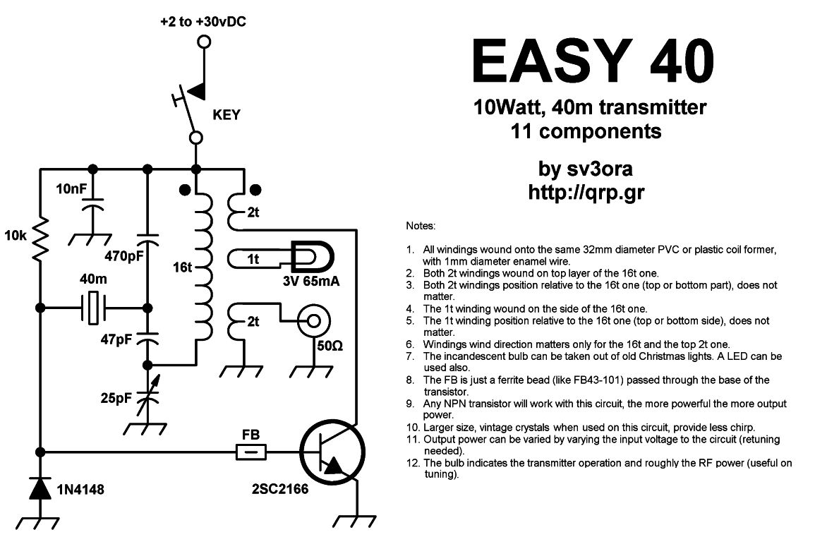
The transmitter construction
The
schematic of the transmitter is shown below.
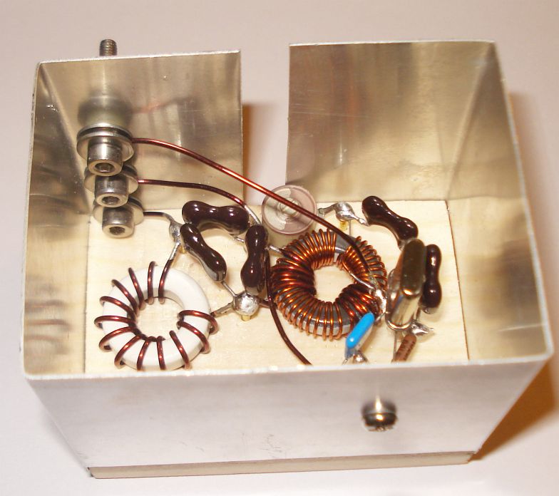
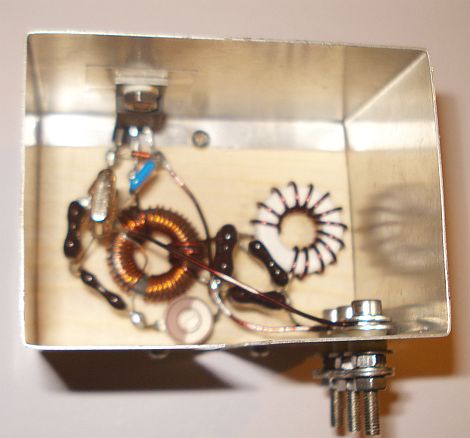
The inductor at the base of the transistor, is just an FB43-101 ferrite
bead, passed through the transistor base lead.
The output filter inductor L, is about 850nH. It is wound with 13 turns
of 1mm diameter enameled copper wire, evenly spaced, on an Amidon T68-7
toroidal core.
The transformer T, has three windings (T1, T2, T3) and it is made the
following way:
- Take a piece of 0.5mm diameter enameled copper wire and
wind 39 turns, evenly spaced, on an Amidon T68-7
toroidal core. This is the T1 winding.
- Then take a piece of 1mm diameter enameled
copper wire and wind 4 turns on one side of the same
toroidal core. These 4 turns are wound on the top layer of the 39 turns winding.
This is the T2 winding.
- Finally, take another piece of 1mm
diameter enameled copper wire and wind another 4 turns,
onto the same toroidal core. These additional 4 turns are also wound on
the top layer of the 39 turns winding, but on the opposite side of the core, than the previous 4
turns. This is the T3 winding.
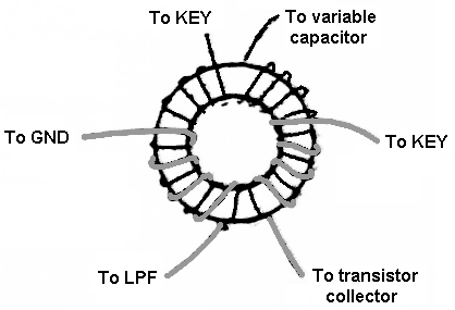
It is important to wind all three windings of the transformer in
the correct phase. That is, the beginnings and endings of the wires
must be wound exactly like shown in the picture below. For example, for
T1 winding, the wire must start from the KEY position and pass in front
of the
core (not hidden below it), then inside the core. The other end of the
T1 winding, should
then go to the variable capacitor, leaving the core from it's back side
(hidden below it). Each time the wire passes from inside the core, this
counts for one turn.
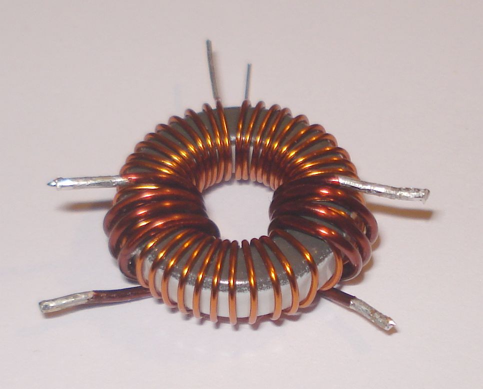
The picture
below, shows the finished transformer and the phasing (direction of
winding) of the wires can be clearly seen.
I
suggest you to use FT-243 crystals or older big crystals with this set.
The tiny modern crystals, while they do work, they produce much more
chirp (frequency drift when keyed) because they are heated much more
than the bigger older crystals.
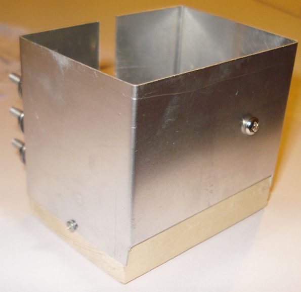
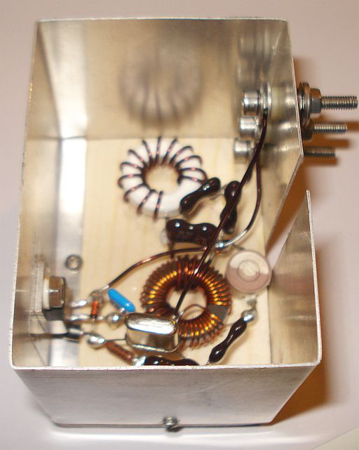
The
enclosure of the transmitter is purely homebrew. Not only it looks
better than the commercial enclorures, but it is also very cheap, easy
to build, lightweight, in the right dimentions and plays an important
role on both the mechanical and the electronic construction of the
circuit. It has been made using a wooden base (breadboard), which
holds the components using nails and metal walls that are made out of a
single thin
sheet of aluminium, cut and bent to the right shape. The
aluminium sheet is thin enough, so that it can be easily cut using a
pair of scissors and bent using finger pressure and a ruller.
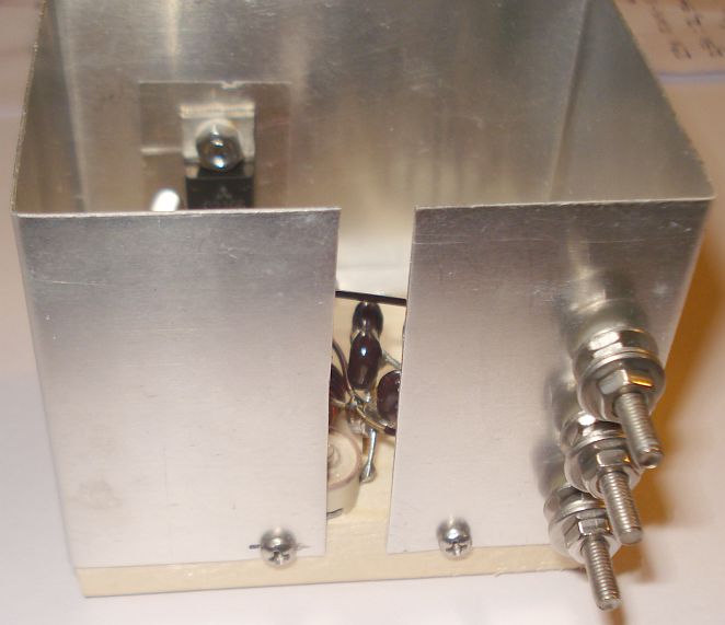
The aluminium walls, host the connectors for the transmitter, but they
are also used as a heatsink for the transistor, eliminating the need
for a separate heavy, bulky and usually expensive heatsink. The tests
have
shown that even this thin sheet of aluminium, can easily take the heat
apart from the transistor, even at high power levels and prolonged
transmitting times. Note that in this transmitter, it is best to
electrically insulate the aluminium heatsink from the components, so a
piece of mika thermoconductive insulator was used in conjunction with
plastic-ring screw insulator, to attach the transistor to the heat
sink. Thermoconductive paste, is absolutely not necessary to be used,
althought it is not a bad idea to use it if you have it on hand.
Since
one of the goals was to make a cheap transmitter for the field,
expensive connectors are not used. For the power and the antenna
connections, ordinary cheap (but high durability) stainless steel
screws, nuts and bolts were used, to create the
connectors. The screws are larger in length, to allow both crocodile
clips and bare wires (using locking nuts and bolts) to be easily
attached. This solution is highly durable (large number of connection
cycles) but more importantly it is cheap and very convenient in the
field, where suitable coaxial connectors are not always available and
there is a high risk to forget taking compnents with you.
However if using it with coaxial cable from inside the shack, you may
want to make yourself (or buy) a wire-to-coaxial adaptor, to avoid RF
leakage in the shack. The output of the transmitter is 50 ohms, so you
would need no matching to the coaxial cable. Most possibly, your
antenna would need matching to 50 ohms at HF, not your transmitter.
Just as in the transistor case, the screws of the connectors (even the ground) must be
isolated from the aluminium heatsink, to minimize hand effects and
ensure stable operation. For insulators, a few pieces of transistor
insulating plastic rings were used.
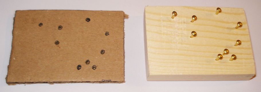
The
circuit is made in breadboard-style onto a piece of wooden base, cut in
the right dimensions, which also serves as an electrical and thermal
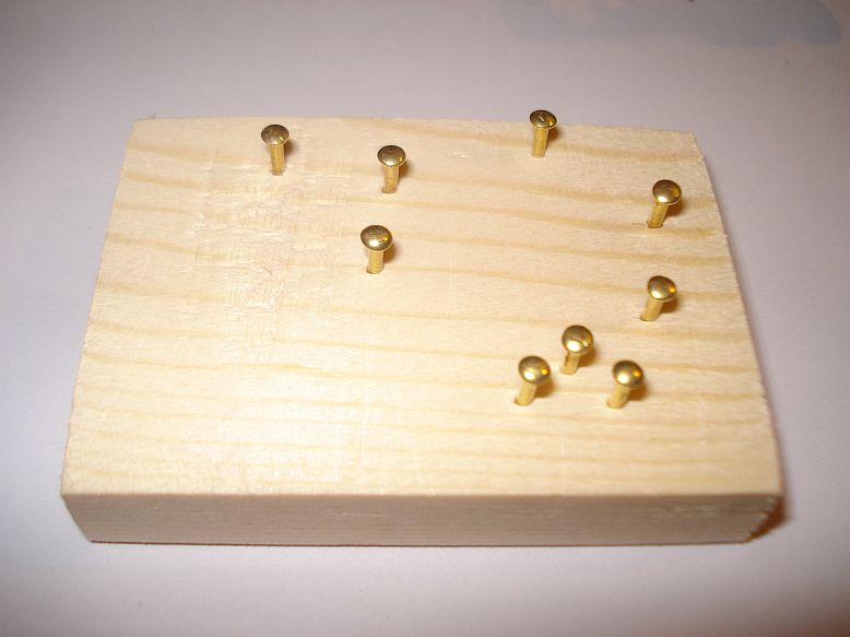
insulation between components. Nine solderable nails, nailed onto the
wooden base, serve for the mechanical stability of the components and
help solder the components leads together.
The nails positions are not arbitrary. They are placed like this, to
achieve minimum connection lengths between components and avoid the use
of extra wiring. To make it easier for you to place the nails, I have
created a template. Simply put the template onto the wooden base and
nail the nails onto the wood, at the predefined positions.
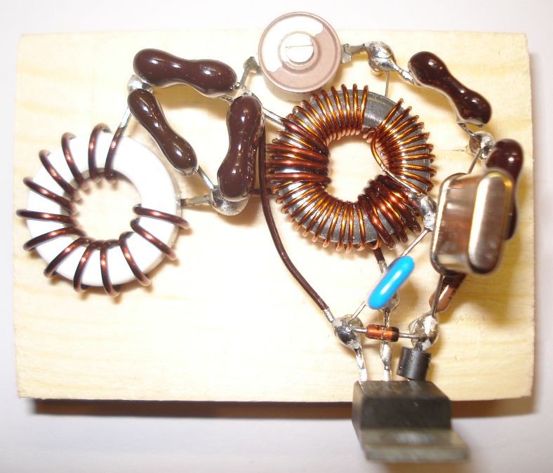
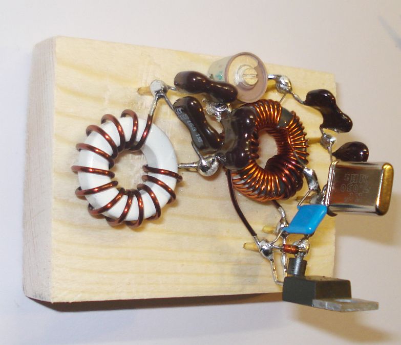
The
next pictures, show all the components of the transmitter, soldered
onto the wooden base nails. This construction may look ugly, but from
the RF point of view it is optimal, since the connections between
components are minimized.
Since
the output power of the transmitter can be varied by varying Vcc, the
transmitter can be easily AM modulated, by replacing the key with a
series connected transformer, as shown in the schematic below.
I have
tested this configuration with a small series transformer, taken out of an old TV
speaker, which has a primary of 4 ohms (audio amplifier side) and a
secondary of 120 ohms (transmitter side).
To drive this transformer, a TDA7360
integrated amplifier, working in bridged mode and driving the 4 ohms
primary directly, thought to be a simple way. Indeed this class-AB
amplifier combined with the transformer modulator, form an efficient AM
modulator. If efficiency is the goal, this is the way to go. However,
this approach requires three additional components for the modulation.
A suitable audio transformer (which is not always available and easy to
find), an amplifier IC and a separate PSU for this amplifier (TDA7360
works on 18V max).
If
efficiency can be sacrificed though, AM modulation can be achieved with
a series BJT or FET in place of the transformer. Similarly, an LM317
can be used and this can double it's use as an AM modulator as well as
a variable PSU for the transmitter (to vary the output power of the
unmodulated carrier). Since the goal of this transmitter is simplicity,
this can be an acceptable way.
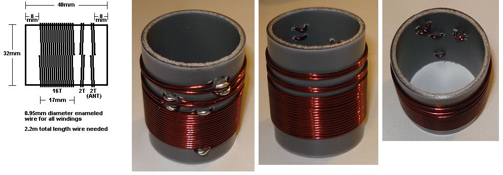
I
have even tried to make a coreless transformer for this transmitter. It
worked but it produced much mess power. However, I did not have the
time to optimize the turns ratio, but at least I got the phasing of the
windings correct. Anyway, here is the construction of the coreless
transformer for anyone interested.
Back to main site