HF directional
coupler
by SV3ORA
During the construction of a signal generator, I needed a way to keep it's output signal amplitude stable, so I needed an ALC circuit. This involves taking a small sample of the output signal, rectifying it and driving a level control circuit, to control the oscillator gain. If a simple resistive sampler or a transformer sampler is used in that case, not only the output signal of the generator will be sampled, but also the reflected signal, if the generator and load are not perfectly matched. A directional coupler, used as a signal sampler, can easily solve this problem.
A directional coupler separates signals based on the direction of signal propagation. These devices are used to unequally split the signal flowing in the mainline and to fully pass the signal flowing in the opposite direction. In an ideal situation some portion of the signal flowing into port "In" will appear at Port "Coupl". Likewise any signal flowing into port "Coupl" will be coupled fully to port "In". However ports "Coupl" and "Out" are isolated in the sense that any signal flowing into port "Out" will not appear at port "Coupl" but will feed through to port "In".
Directional couplers are impedanceless, in the sense that they become 50 ohm, or 75 ohm, simply by matching all ports to either 50 ohms, or 75 ohms, respectively. Directional couplers are usually implemented using two toroidal transformers. Alternatively, ferrite binoculars can be used to implement both transformers on a single twin hole ferrite core.
 |
|
|
|
|
 |
Out | |
|
|
|
|
|
|
 |
 |
|
 |
|
|
In |  |
|
 |
1t | |
 |
|
 |
|
|
|
 |
|
10t | |
|
|
|
|
|
|
 |
|
|
|
|
|
10t |  |
 |
|
|
 |
|
|
|
 |
|
 |
1t | |
|
|
|
|
 |
|
 |
Coupl. | |
|
|
|
|
|
|
|
|
|
|
|
|
|
100R | 100R | |
|
|
|
Low frequency response is dictated by the ferrite material characteristics. In my prototype above, I used BN-43-202 binocular core. High frequency response is partially governed by total wire length, since the core effects are no longer dominant near the high frequency end, but for HF it doesn't matter too much. Interwinding capacitance, leakage inductance, copper losses and transformer coupling below unity (k <1) also degrade high-end performance. Small shunt capacitances to ground at the coupler ports can be used to improve match and directivity at the expense of bandwidth. At higher frequencies, lead length must be kept to a minimum to limit parasitic inductance. To achieve broadband performance, ground connection lengths must be minimized. Increasing the number of turns on the primary is limited by the number of wires that can fit through the core. High frequency response increases as core size and wire diameter decrease.
The response of the directional coupler can vary dramatically depending on the interleaving of the primary and the secondary coils. If possible, intersperse the secondary windings with turns from the primary. Designers will often set the spacings of the primary and secondary coils to optimize certain design parameters. Changing the diameter of the primary wire relative to the secondary changes the coupling by tenths of a dB. Using heavier gauge magnet wire for the primaries reduces mainline insertion loss and improves power-handling capability. The isolated port should connect to a good Zo ohm load impedance, such as a small chip resistor or other non-inductive standard resistor types. A small capacitor in the range of 0.5 - 2 pF can be connected in parallel with this resistor to improve directivity.
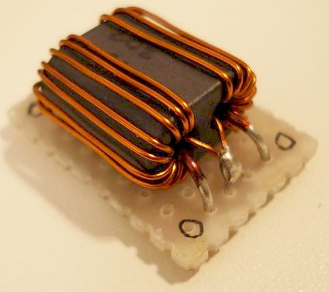
Figure above, shows how the windings must be wound for a 3:1 turns ratio. In my prototype, I used 10:1 turns ratio and I also wound the 10 turns, not on top but on the sides of the core. See the images below and you will figure out how this can be wound.
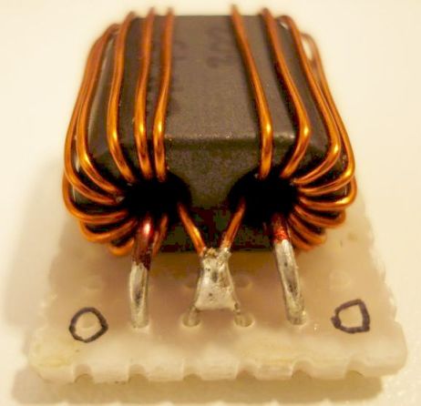
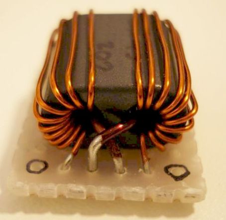
To strengthen the construction, a small piece of prototype board was used to solder the end connections.