Simple MCU-free HF frequency counter
by sv3ora
An RF frequency counter is a very useful instrument in the lab and it is used in a daily basis from the experimenters. In the past, I have built several different frequency counters, all of them using microcontrollers and LCD displays. This time I took my chances to build an RF frequency counter that is MCU-free. Usualy, such projects require lots of TTL chips. However, recently I found a design of a very promising counter that required only 8 TTL chips. Here is the original article for the counter, prior to my modifications. In this page I won't repeat all the information in the article, but I am going to show you how I built my version and also the modifications that I did. Note that I have corrected a few errors in my version and I also did some modifications in the original schematic.
So what is
the point of building an MCU-less frequency counter nowadays? Nowadays,
with the improvements in MCU technology, a frequency counter with good
characteristics can be made at very low cost. It almost makes no sense
to try to build TTL frequency counter. But for the homebrewer, the
situation may be quite different. There are various reasons for that.
The microcontroller requires a programmer hardware and software, in
order to be programmed. A PC is also required for the programming
operations. Quite a few of the homebrewers do not know how to write a
program for the MCU and learning MCU programming is difficult for many.
Thus, they rely on programs others have built and they cannot alter
their operation to their needs. Even the cost of the MCU chip that
might initially be thought as low, can be proven to be much higher at
the end, with all those mentioned requirements.
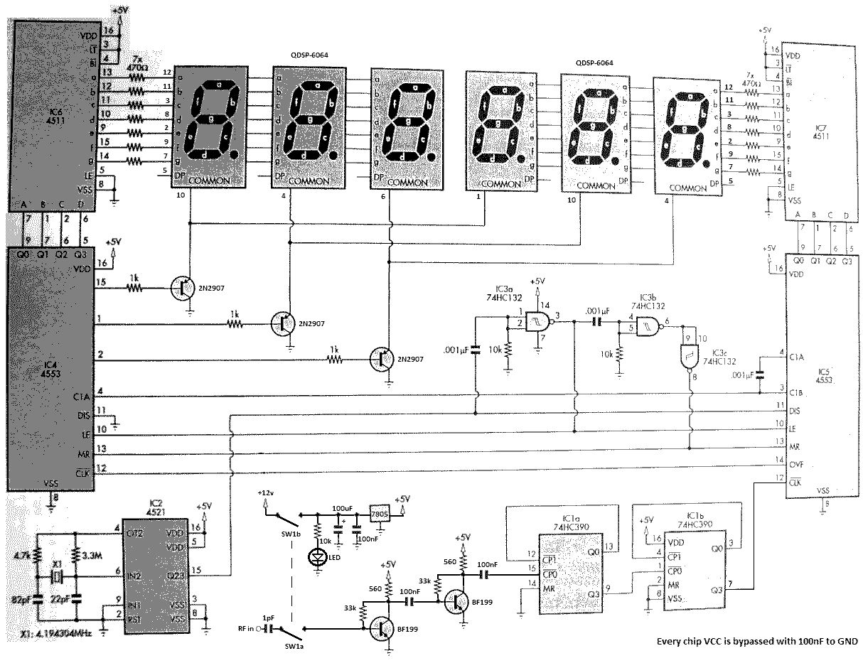
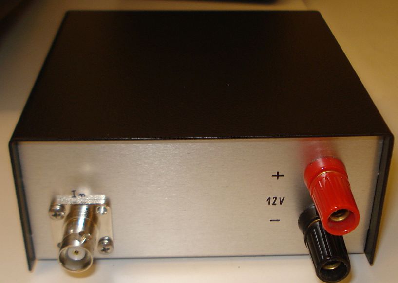
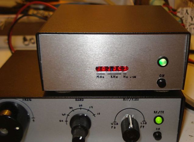
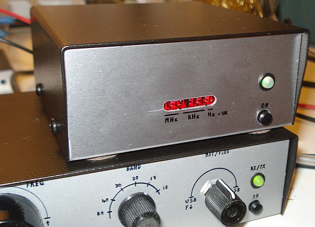
With the modifications I have made to the original circuit, my frequency counter is capable of operation to 40MHz with 100Hz resolution and it uses one chip less i.e. 7 chips in total. It is a true RF frequency counter, not just TTL and it is very sensitive. It has very high isolation from the circuits connected to it. This means that it does not output any parasitic signals to them, neither it affects them in any way. Simply put, connecting the counter to an oscillator circuit, does not affect the frequency or the level of the oscillator and it does not induce any other frequencies to it. The On/Off switch not only switches the counter power, but it also connects/disconnects the counter input, to ensure maximum isolation when the counter is not used, without the need to unplug from it the connected coaxial cable.
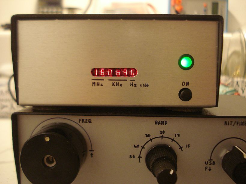
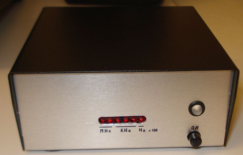
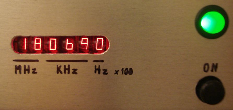
You may use any suitable type of seven segment displays you like with this counter. However I hapened to have a few of these vintage HP QDSP-6064 "bubble" displays, taken out from old HP calculators, so I used them. These make a very neat little display for the counter. They have 4 digits, so I used two of them (8 digits in total) and I left two of the digits out.
The 74HC132 could be replaced by discrete gates if you like to reduce the total number of chips to 6. However my experiments were not very successful and since this chip is quite common, I decided to leave it there.
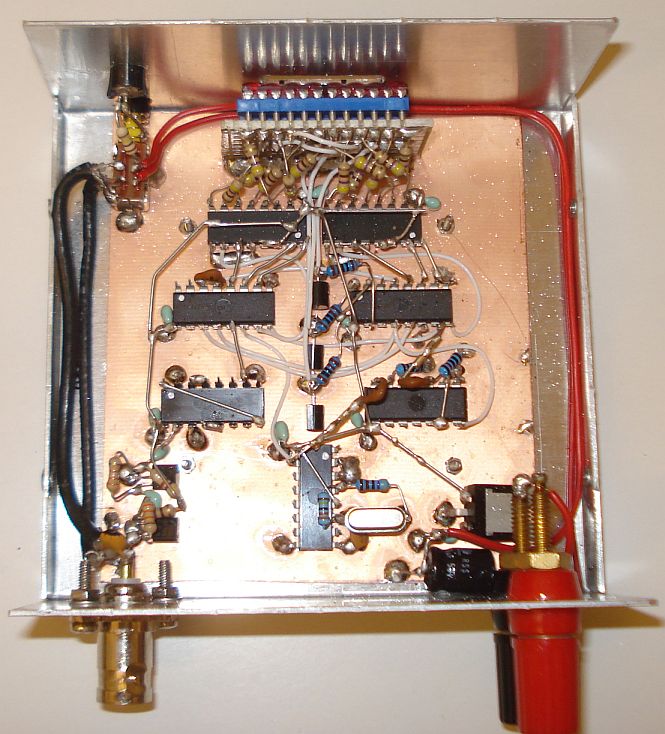
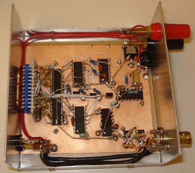
The counter was built into a metal enclosure to reduce any possible interference from it to the near-by circuits. The small display used, needs only a very small hole to be made onto the enclosure, which helps in that aspect.
The counter was built "dead bug" style without any PCB. The chips were placed upside down with their legs faced upwards and the cables were soldered directly onto them. The GND and decoupling capacitors leads were useful for keeping the chips in place onto the copper clad board piece.
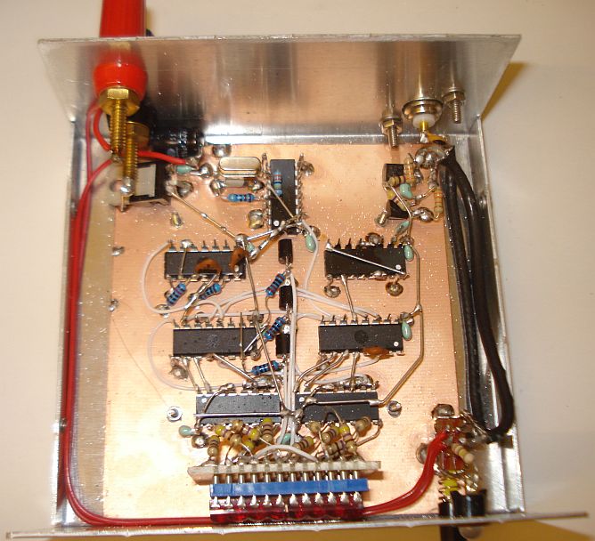
A small piece of proto-board accomodated the displays. I used sockets for these, to avoid ruining them, as these are vintage. I also included a 5v regulator, to isolate the DC from the rest of the circuits connected at the same DC line and to provide a stable DC voltage to the counter.