
by SV3ORA
Magnetic receiver
by SV3ORA
Introduction
The current page investigates some very unique properties of transformers and attempts to apply them in practice, by trying to build a complete simple receiver.
The initial kick start came to me when I discovered the website of AA1TJ, presenting a saturable reactor ferrite core mixer for VLF. I always believed that transformers are hiding very interesting secrets not known by most people today. These big and bulky blocks that most of us try to avoid, are marvelous devices and their applications are much more than transforming voltages and currents.
I started searching on the internet about saturable reactor ferrite core mixers and I came up with a few number of articles describing the operation of the transformers, one of them being the non-linear operation of the transformers when saturated, and the other their use as amplifiers. The Transformer Book by Lee Reuben and Magnetic Amplifiers by Mali, are two of the best books describing the operation of these devices.
Mixer and LPF
After this mini search, I have decided to make a practical circuit to demonstrate the capabilities of transformers. Since there was already a mixer schematic that has been built by AA1TJ, I have decided to design a simple receiver by trying to use transformers. So far, this is how it looks like.
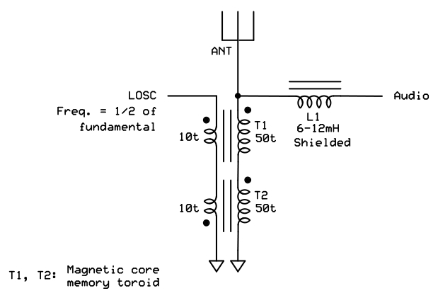
The core of the receiver is a Polyakov harmonic mixer that is formed by two small ferrite transformers, operating in their non-linear region and saturated by the presence of a powerful BFO signal (LOSC). It's main carrier is half in frequency than the actual receiving frequency. The BFO signal must be powerful enough (mine was a little bit more than 2Vpp) so the cores are saturated. If the cores are not saturated, they do not operate in their non-linear region, so no mixing occurs and no down conversion.

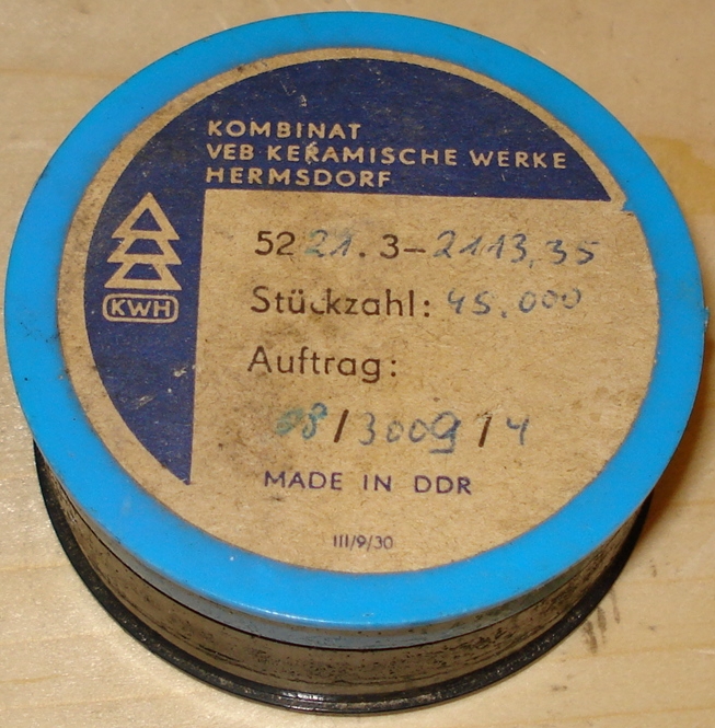
The toroid cores of the transformers are very tiny (a little bit more than 1mm external diameter) and you have to carefully wind 50 plus 10 turns on them. They have been taken out of an old computer magnetic core memory. The coil wire has diameter of about 0.03mm-0.04mm, less than a human hair, so obviously very careful winding has to be done, but it is totally feasible. I believe, the cores have to be so small, so that they can be easily saturated by a relatively small power BFO signal. I have also tried bigger size cores (about 5mm external diameter) with 100 turns instead of 50 and I was still able to receive some stations, but my judgment is that the sensitivity was lower using these bigger size cores. Just try the smallest cores you have, to see how it goes, or order some cores from me.
The RF signal out of the antenna, passes through the mixer and mixes with the BFO signal. The mixer then produces (among many others) the desired down converted audio signal, fed onto L1. At one end of L1 all signals are present, RF and audio. L1 behaves as a low pass filter that cuts-out the higher frequency signals and allows only audio signals to pass through. Without L1, a following audio amplifier, would amplify (and rectify through the B-E junction) RF as well.
You will notice that a shunt capacitor is missing on one end of the L1. After simulation, I have found that a series inductor, without a shunt capacitor, do form a low pass filter as well, but it rolls-off much more slowly. Since audio is far apart from the MHz frequencies, a single inductor is adequate there.
When I used an unshielded coil for L1, I noticed that this coil picked up some FM stations as well (maybe mixing the picked RF with some of the BFO harmonics?). When I replaced it with a shielded coil, the FM stations disappeared. To avoid such situations, you may want to use a shielded coil or place your receiver inside a shielded enclosure. The value of L1 is not critical. I happened to have a variable coil of 6-12mH but you may use anything from 3-15mH. At large coil inductances you can actually start to listen to the effects of filtering at the highest end of the audio frequencies.
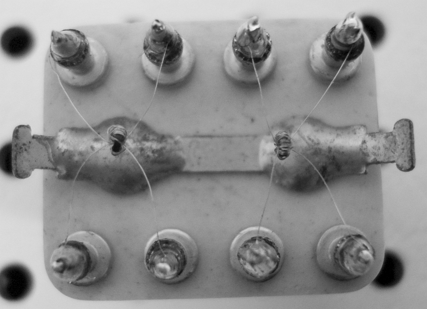
The construction of the mixer has been done on a ceramic frame with pins passing through it for connecting and holding the transformers in place. I used a ceramic frame for lower losses but you may use ordinary PCB or any other non-metal non-magnetic material you like.
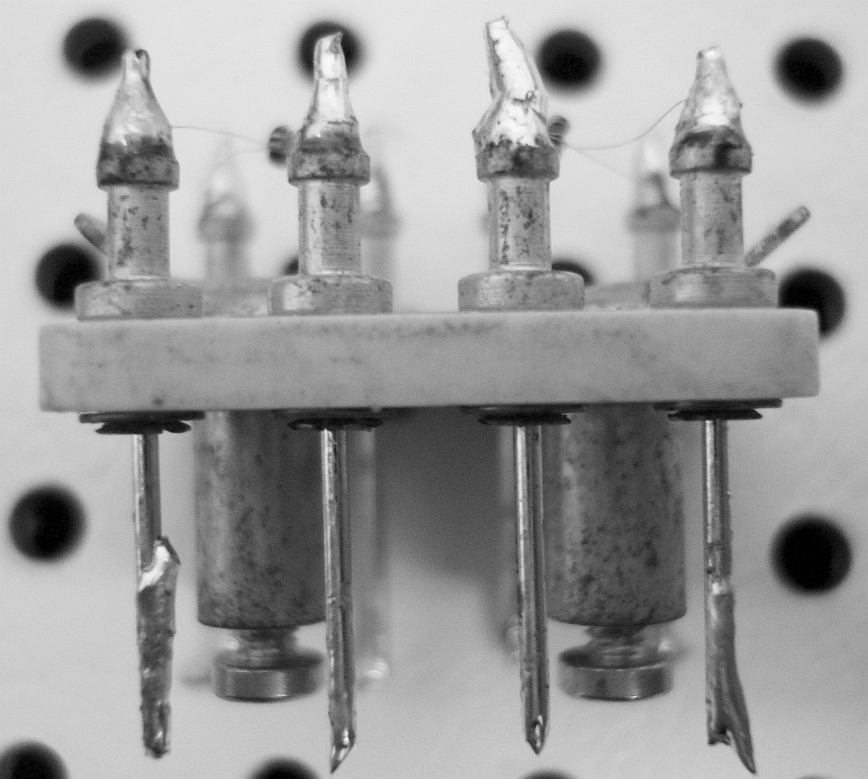
The ceramic frame is attached to the enclosure using two screws. The whole construction is rigid, although care has to be taken not to break the thin transformer wires when touching them.

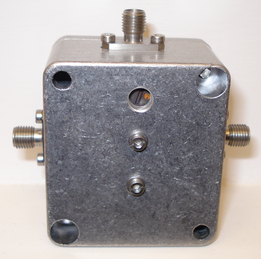
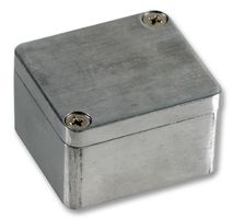
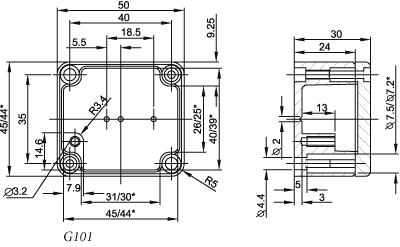
The whole construction is enclosed inside a Gainta G101 die cast box, the smallest of the G-series. It's dimensions and look, are shown below.

To test the mixer, I connected a half frequency oscillator signal, of a little bit more than 2Vpp amplitude, to the LO port of the mixer. I first tried the MW radio band. At night, radio stations came in powerful and I was able to receive 6-10 stations in the MW band. A 90dB audio preamplifier at the output of the mixer fills in the band with many radio stations.
This mixer is able to demodulate SSB and CW. To listen to AM, you have to tune the local oscillator right at the AM carrier signal frequency.
MW radio station slightly tuned out.wav
MW radio station tuned in and out.wav
New version of the mixer
I tried to apply a little bit of DC to the local oscillator transformer winding, to see if I could saturate the cores more, without the need for extra RF power. Then I blew up the mixer, because I had not used a limiting resistor and the current was too much for the thin wire to withstand. I paid the price well, I had to wind another set of transformers that took a whole afternoon. The good thing is that I ensured that way, that the mixer can be reproduced many times with similar results.
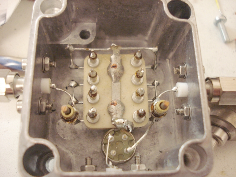
This time I was more careful. I used a 1nF capacitor to feed the local oscillator signal to the mixer and another 1nF to feed the RF to it. I have also used a 100nF capacitor (not shown in the picture above) to take the audio out of the mixer. These changes effectively isolate the mixer from any DC component.
The performance was similar, but I have to do more tests to confirm that. I have also tried to drive the mixer with a 500mW-1000mW local oscillator amplifier and I got some results which I need to verify. I would like to find the optimum local oscillator power point of driving the mixer. More to come...