Audio compressor
Built on 2010
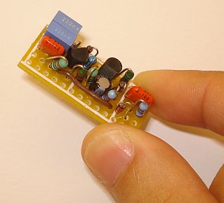
I have build this compressor and it worked at first time. The audio signal goes through C1, R1, D1, C2, R3. Still a part of audio signal charge the D3/D4 detector and creates a control voltage for T1. The fading time depends on C4 and R5. With an audio input variation of 50dB, the output signal get is +-3dB. You can use this audio compressor circuit in a SSB transmitter. I used 1N60 diodes that I could more easily find. I have not tested this using more commonly available diodes but I do not see the reason why this should not work using them.