A universal variable VCO
clock
by SV3ORA
Introduction
A crystal oscillator is usually the solution when dealing with clocking microcontrollers at specific frequencies,
especially the ones that lack the existence of an internal RC
oscillator. If a different frequency is required, a different crystal
must be used. The oscillator that is presented in this article, is
universal, in the sense that it can be easily set at any desired
frequency between 1KHz and 53MHz, without changing any of the hardware.
This allows for rapid testing of your firmware at different
frequencies.
However, such an oscillator is not only limited to microcontrollers use. Broadband switching type mixers, can be built with ICs like the 74HCT4066 or similar and these ICs are better driven using square wave local oscillators. This allows for future development of broadband direct conversion receivers at a very low cost and complexity.
Of course there are
dedicated ICs that can be used as variable clocks like the Si570 or DDS
ICs. However, the cost of all these ICs is high and they require complex
programming for setting their frequency. While these ICs have very good
frequency stability (because they depend or contain reference crystal
oscillators), in many applications, extreme frequency stability is not
required.
Implementation
The core of the oscillator is an LTC1799 IC. This little 5-lead plastic TSOT-23 is a very wide range resistor set oscillator. An oscillator that can be set at a very wide range of frequencies, using a single resistive element and avoiding big and bulky variable capacitors, hard to find varicaps and complex programming, should not be underestimated.
Theoretically, the frequency stability of the oscillator should be good but one has to be extremely careful to prevent any noise or hum pickup on the resistor wiring. If a variable resistor is used for tuning, it has to be a good quality one with low temperature coefficient. For fine frequency adjustment, a multi-turn variable potentiometer could be used, but then another problem arises. The inductance of these multi-turn potentiometers is high because the resistive element inside them, is usually a helical wound wire. This leaves the only profound solution to be the small multi-turn trimmers.
A better way exists though, one that helps not only to minimize the noise of the resistive element, but also to convert the oscillator into a VCO. This utilizes the use of an LDR and a LED as a tuning element. The LDR is a true resistive element (in contrast to FET variable resistors) of low inductance and zero mechanical noise. Because of it's small size, the LDR can be mounted very close to the IC, which is very important as well. Being transformed to a VCO, the oscillator can be further locked to a PLL or FLL source, for excellent frequency stabilization. The schematic of the oscillator is shown below.
 |
VC | |
|
|
|
+5v | |
|
|
|
|
|
|
|
 |
|
|
|
|
|
|
|
LTC 1799 |
|
|
|
|
|
 |
180 | |
 |
 |
 |
 |
|
 |
|
 |
out | |
| 10k |  |
|
 |
 |
|
100nF |  |
1 |  |
5 | |
|
|
|
 |
LED |  |
 |
vt43 n1 |
|
|
|
|
|
|
|
|
|
|
|
|
|
|
|
|
|
|
|
|
|
+5v |
|
|
|
|
|
|
|
|
2 | |
|
|
|
|
|
|
|
|
|
|
|
|
|
|
|
|
 |
 |
|
|
|
|
 |
|
|
|
|
 |
|
|
 |
NC |
|
|
|
|
|
|
|
|
3 | |
4 | |
|
|
|
|
|
|
|
|
|
|
|
|
|
|
|
|
VC is the control voltage of the VCO, which can be different or isolated from the power supply voltage. If VC is connected to +5v, then the oscillator frequency is controlled from the 10k multi-turn trimmer. However, if VC is connected to a PLL or FLL stabilizer output, then the oscillator frequency is controlled from the stabilizer. In that case, the multi-turn trimmer and the 180 ohm resistor must be adjusted so that the LED turns from fully off to fully on throughout the whole tuning voltage range of the stabilizer.
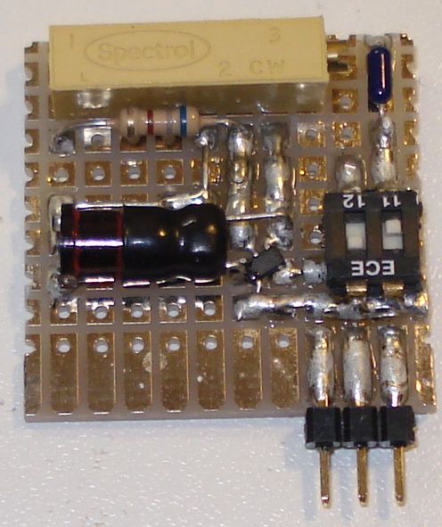
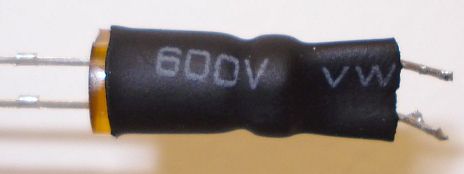
The multi-tap switch, sets the range of the oscillator and it's middle tap is left unconnected. To minimize size, a two-position DIP switch was used in the prototype. The LED and the LDR must be enclosed into a light-proof enclosure, with the LED pointing towards the LDR. In the prototype, a thermal shrink tube was used as an enclosure and the whole structure was held together like shown in the picture below.
The results of the
oscillator operation are shown in the next pictures, for different frequencies.
The datasheet states an operation range from 1KHz to around 30MHz. However in
the prototype, oscillation started reliably between 270Hz and 53MHz. The signal
levels are always TTL, but above 30MHz the levels start to drop and reach
2.65Vpp at 53MHz. The square wave shape is quite good and acceptable up to 14MHz
but above that, it becomes distorted. At 28MHz the waveform shape is more like a
distorted sinewave, whereas at 53MHz it is more like a triangular. All
measurements were performed at 1Mohm oscilloscope. At 50R, the oscillator showed
similar performance to the 1Mohm, up to 30MHz.