A low frequency circulator/isolator for lab measurements and signal routing

by SV3ORA

Preface

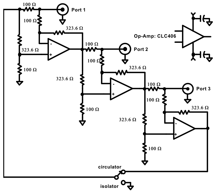
A circulator/isolator is a very important piece of equipment for any microwave RF laboratory. It can be used in many ways, from impedance matching of antennas and in-circuit blocks, to signal routing and isolation. Whereas a circulator is a microwave component that uses ferrites in the signal path, modern opamps have allowed such a behaviour to be made available (for low signal levels) in the lower frequencies as well, of course not by using lossy ferrites, but using opamps. Until I built this circulator, all my efforts to achieve inter-stage or antenna impedance matching to 50 ohms, where theoretical and experimental.

The original design of this circulator is credit of Charles Wenzel, thus many of the things from the original article will be repeated here. I have just added my own power supply design, the PCB and the whole construction into a single enclosure.

Key features of the active circulator/isolator:


Project files

Bottom copper layer (PDF)
Bottom copper layer (ExpressPCB)
G101 enclosure (PDF)

G101 enclosure (DWG)
G101 enclosure photo (PDF)


The main circuit

The schematic of the signal part of the circulator is shown in the picture below. All ports have an impedance of 50 ohms. The isolated 50 ohm resistance presented at each port, makes experiments with non-linear or reactive devices such as detectors, mixers, frequency multipliers, and filters straight-forward since both the signal source and the analyzer are isolated from the device under test.

High reverse isolation, ensures that the energy flows in one direction around the circulator and that the impedance of one port is not affected by the other ports. Since the circulator works down to DC, its behavior can be observed with a
multimeter. The port resistance can be measured with an ohm-meter and during the measurement the ohm meter's test voltage appears at the next port (inverted).

If -1 VDC is applied to port 1, then 1 VDC will appear across 50 ohms at port 2 and 0 VDC will appear at port 3. But if the load is removed at port 2, then the 1 VDC will "reflect in phase" and constructively add, to give 2 volts at port 2 and the reflected 1 VDC will appear at port 3 (as -1 VDC due to the op-amp inversion). Now if port 2 is shorted, then the 1 VDC will "reflect out of phase" and will destructively add to give 0 VDC at port 2. This inverted volt,  circulates  to  port 3, where +1 VDC appears across the load.

Stable, low inductance precision resistors are required for optimum results. The 323.6 ohm resistance can be achieved by paralleling a 330 ohm with one of about 16.8 kohm. The resistor values shown may be scaled to build a circulator with a different characteristic impedance. For example, a 75 ohm circulator would use resistors 1.5 times larger in all positions. It is interesting to note that a circulator could be built with a different characteristic impedance at each port.

The CLC406 op-amp selected for this design is not the fastest or highest power device that Comlinear Corporation manufactures, but instead represents the economy end of the spectrum with a price below $10. A better choice would be to select a faster, more powerful op-amp from the many available today. I used the original opamp described by the author, only because he had performed actual measurements on this one. These measurements can be summarized in the following diagrams.


The power supply

As can be seen from the previous diagrams, the performance of the circulator is mainly depended on the power supply. The choice of the power supply is quite tricky. Generally, the greater the voltage, the better, within the limits of the opamp. On the other side, the use of a dual rail (positive/negative) PSU required by the opamps, imposes complexity and a negative PSU may not always be available.

In order to use a single +12v power supply, a converter must be made, to convert this single rail PSU to a dual rail one, providing +v, 0v(GND) and -v for the opamps. It is important to note that a "virtual ground" converter composed of capacitors or specific purpose chips, cannot be used in this circuit, because of GND and RF enclosure isolation issues. The only feasible solution is a charge pump capacitor circuit, to generate the nagative voltage. Hopefully, the current drawn by the opamps is low, so the voltage drop is within the operating limits of the CLC406 opamp.


The circuit of the PSU designed, is shown in the picture above. Both the positive and the negative potrions of the PSU are regulated. The tricky bit, is to keep the ballance of the two portions as good as possible, independently of the current drawn by the opamps when signals are present and when not. The two zener diodes serve for this purpose. They sacrifice some voltage, to ensure relatively stable negative and positive voltages, regardless of the current drawn by the opamps.

The use of the 10k potentiometer is not mandatory and this can be probably replaced with a single resistor. Although, I left this potentiometer there, to be able to adjust the regulation, in order the transistor to run cooler without the need for a heatsink. This was also the main reason I used a power transistor with higher dissipation, although it was not actually needed. I could also have the regulators removed and just keep the zeners there, but the use of the regulators ensures cleaning of the voltage and isolation of the outputs from the previous components of the PSU. Also, connecting the zener at the collector of the 2n2907 transistor, dropped the voltage too much, so I decided to leave it connected at the emitter.


Overall construction

The circulator is composed of two PCBs, connected together in a modular way, so that they can split apart if needed. The bottom PCB is the PSU (apart from the zenners), whereas the top PCB is the circulator circuit. If one decides to feed the circulator with a dual rail supply directly, then the PSU PCB can be left out and the zenners can be replaced by higher voltage ones, to improve the characteristics of the circulator.

In the next pictures, the construction of the PCBs is shown. The DIP switches are used to switch the circulator/isolator option. The zenners are not shown in these pictures, as they have been soldered at a later time.


The PSU PCB has three main connections to the circulator PCB, one for the positive voltage, one for the negative and one for the ground. There are also other ground connections from the PCB corners, to ensure rigidity and good GND. The two PCBs are sandwiched together, with these connections interconnecting the top and the bottom PCBs.


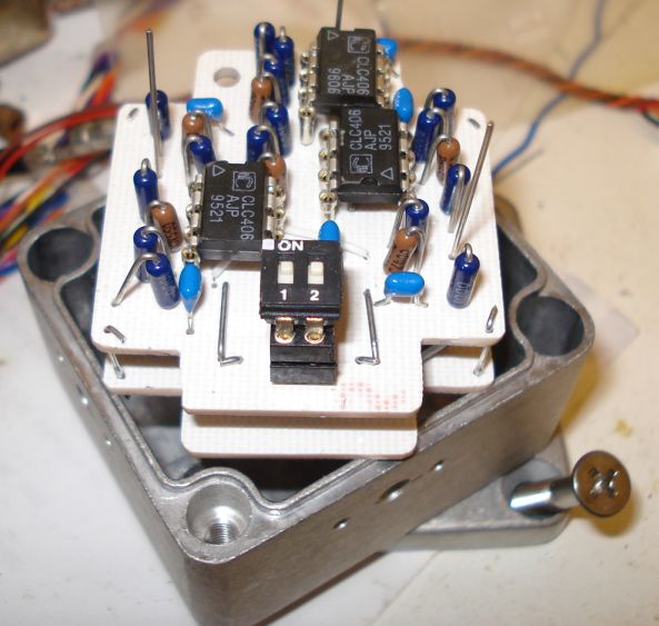
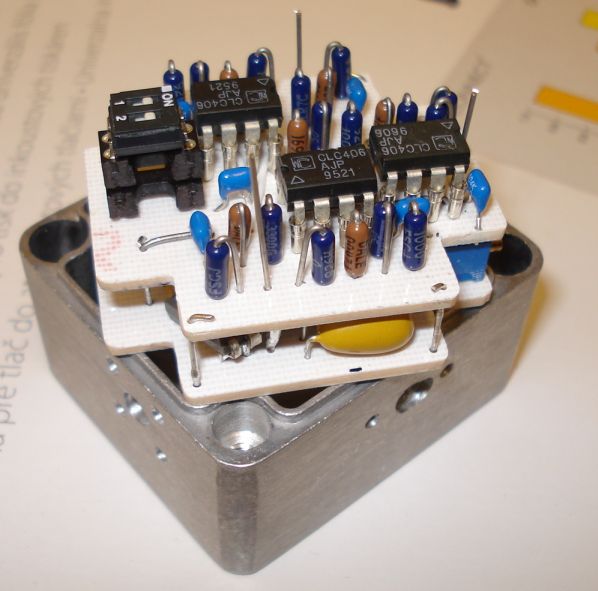
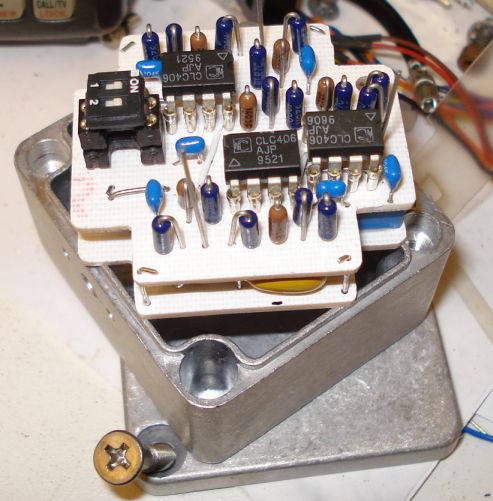
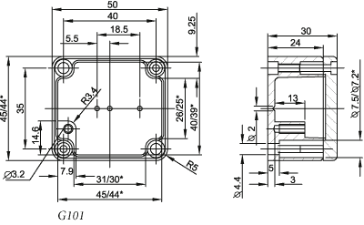
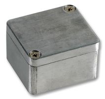
The whole circuit is enclosed inside a Gainta G101 die cast box, the smallest of the G-series. It's dimensions and look, are shown below.

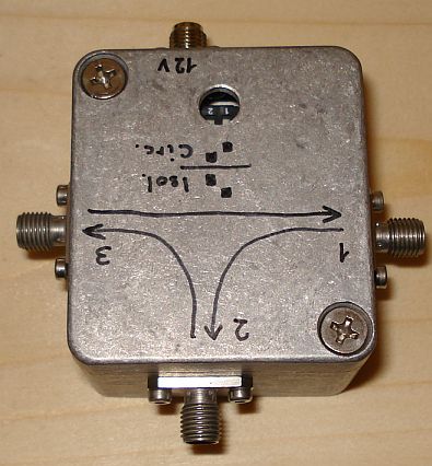
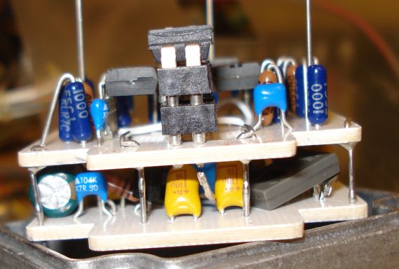
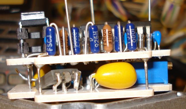
Space inside the enclosure is very limited. The bottom PCB pins are just touching the metal box below. To prevent short circuits, a thick insulating membrane was added between the bottom pcb and the enclosure.

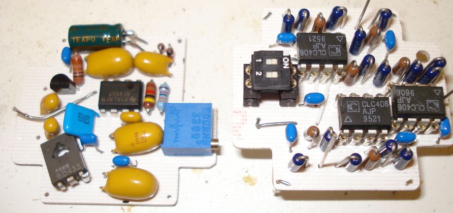
I used SMA connectors for the RF ports and the PSU line because of their small size, but almost any RF connector can be used at these low frequencies. I have chosen to use a coaxial connector for the PSU line, to shield it from external noise. Bare wires used for the PSU line, can pick up external noise and transfer it inside the circulator circuit. A shielded coaxial cable to connect the circulator to the PSU is the best.


Circulator applications

The circulator is a natural choice for the matching and tuning of low level amplifiers. With the signal source connected to port 1, the amplifier's input or output to port 2, and a signal analyzer to port 3, the amplifier is tuned for maximum return loss by adjusting for minimum signal at port 3. A high return loss is synonymous with a good VSWR since a well matched amplifier will "return", as a reflection, very little of the input signal.

Low level signal sources may also be adjusted for 50 ohm output impedance in a similar way. Simply adjust the frequency of the test signal until it is close to the carrier then tune the source for minimum reflection. Again, the reflected signal appears at the next port. If the source's amplitude is too high for the circulator's op-amps to handle just add an accurate attenuator. The circulator's accuracy is sufficiently high to "see" the return loss of a source through a small pad. Remember, the test signal passes through the pad twice and is attenuated each time so the return loss will seem better than it actually is by twice the attenuator value. In fact, a pad terminated with an open orshort will exhibit a return loss exactly twice the pad's attenuation factor since the return loss of an open or short is zero.

Antennas may be tuned in a similar manner without using large signals that might cause interference with others. A low power generator is connected to port 1, the antenna to port 2, and some form of power or signal level indicator to port 3. The signal level at port 3 is proportional to the transmission loss and should be minimized by tuning the antenna matching network.

A time domain reflectometer is easily realized by applying a fast square wave or pulse to port 1 and connecting the device or cable under test to port 2. Breaks in the cable or other high impedance anomalies will reflect pulses with the same polarity as the input whereas shorts or lower impedances will reflect inverted pulses. Remember the inversion from one port to the next. A clean test signal is necessary forgood results.

Circulators can be used for many more uses, including decoupling of generator and load of amplifier stages, reducing intermodulation caused by other transmitters, reducing load return loss and vswr, combining two and more transmitters, combining transmitters and receivers on the same antenna, combining amplifier stages in solid state transmitters, operating one-port-amplifiers, duplexing and locking and priming of oscillators. For practical examples about the use of circulators please read the Philips application note.


Can it be made better?

The circulator is quite good as it is, but it could be made even better. A good starting point would be to change the opamps with faster, lower noise, higher power ones. This will probably require a more powerful PSU to be made.


References

Low Frequency Circulator/Isolator Uses No Ferrite or Magnet - Wenzel Associates
Circulators and Isolators, unique passive devices - Philips application note AN98035


Back to main site