All HF bands transmitter design (experiment)
by sv3ora
Schematic of the transmitter section below.

Below is a version where the final BJT is used as an RX mixer. This idea has not been fuly tested.

The VXO arrangement varies the frequency to an adequate range even
at 160m, but does not change the output level much, which is good. The
combination of TX tune and RIT, makes the transceiver capable of
transmitting at either sideband, so you double the chances for a
contact. TX tune and RIT controls almost don't affect each other and
they have adequate and quite even spread.

The version above uses a relay and a separate receiver mixer can be used.
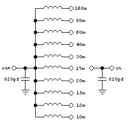
The low pass filter design is shown below.
Band
|
Input/output capacitors
|
Inductor
|
160m
|
820pF
|
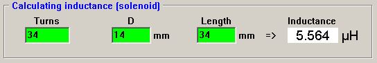
5.56uH
|
80m
|
820pF |
2.58uH
|
60m
|
820pF |
1.61uH
|
40m
|
820pF |
1.05uH
|
30m
|
820pF |
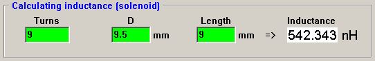
542.3nH
|
20m
|
820pF |
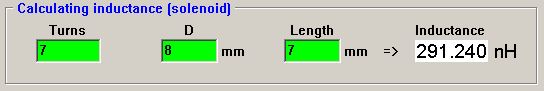
291.2nH
|
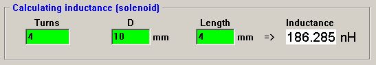
17m
|
820pF |
186.2nH
|
15m
|
820pF |
132.7nH
|
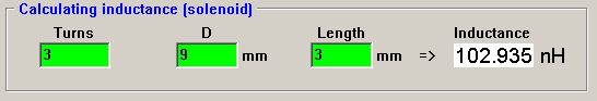
12m
|
820pF |
102.9nH
|
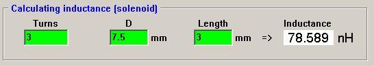
10m
|
820pF |
78.5nH
|
The filter schematic is shown below. All coils implemented with 1mm
enameled wire. Coils are wound onto appropriate diameter
drills, then the drill is removed.
Pictures below, show how to wind the coils. They are all close wound with 1mm enamel copper wire.
160m

80m

60m

40m
30m
20m
17m

15m
12m
10m